Services d'usinage CNC de composants de turbine en superalliage de haute précision
Fabrication de précision pour des applications aux performances extrêmes
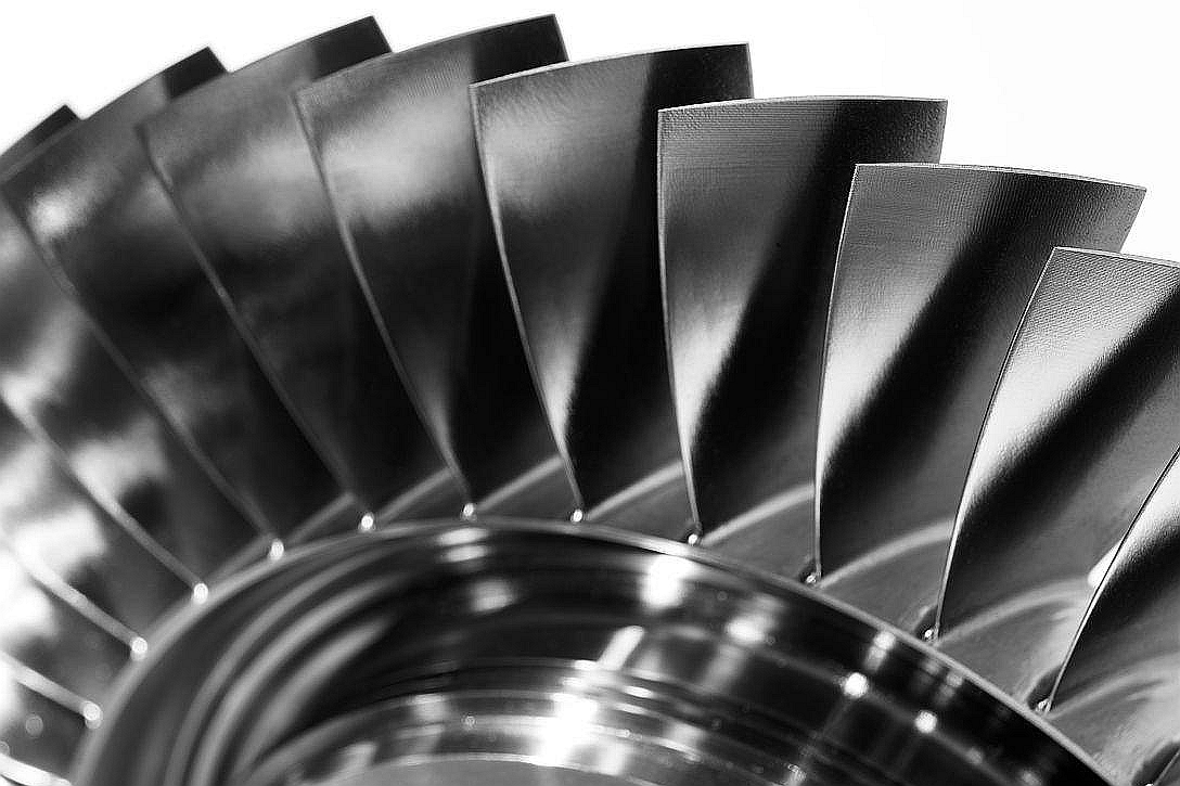
Les composants de turbine en superalliage fonctionnent dans des environnements à haute température, haute pression et haute vitesse, rendant la précision dimensionnelle, la résistance à la fatigue et l'intégrité de surface essentielles. Ces pièces—utilisées dans les moteurs à réaction, les turbines à gaz et les turbomachines—doivent être usinées par CNC avec des tolérances inférieures à ±0,005 mm et des états de surface de Ra ≤ 0,4 μm pour garantir une efficacité et une durabilité optimales.
Neway AeroTech fournit des services d'usinage CNC avancés pour les composants de turbine fabriqués à partir d'Inconel, d'alliages Rene, de la série CMSX et d'Hastelloy, livrant des aubes, des injecteurs, des carters et des écrans thermiques de haute précision.
Technologies clés pour l'usinage de turbines en superalliage
Nos systèmes d'usinage sont conçus pour produire des géométries complexes tout en maintenant une haute précision selon des exigences strictes de performance aérospatiale et énergétique.
Usinage simultané 5 axes pour les géométries complexes de profils aérodynamiques et de plateformes
Palpage en cours de processus et compensation de l'usure des outils pour une précision de ±0,005 mm
Usinage avec broche à refroidissement interne pour contrôler la chaleur et prolonger la durée de vie des outils
Génération de trajectoires d'outils basée sur la FAO à partir de profils CAO et CFD
Tous les services sont conformes aux normes AS9100D et NADCAP pour les composants critiques de turbine.
Matériaux en superalliage pour l'usinage CNC de composants de turbine
Alliage | Temp. max (°C) | Limite d'élasticité (MPa) | Application |
|---|---|---|---|
1050 | 880 | Aubes de turbine haute température | |
980 | 1450 | Aubes de turbine et verrous de racine | |
1140 | 980 | Profils aérodynamiques de turbine du premier étage | |
1175 | 790 | Chemises de chambre de combustion et écrans thermiques |
Ces matériaux offrent une résistance supérieure à l'oxydation, une grande résistance au fluage et une stabilité thermique exceptionnelle.
Étude de cas : Usinage CNC d'un rotor de turbine en Rene 88 avec géométrie multi-axes
Contexte du projet
Un fabricant de turbines nécessitait une tolérance de profil de ±0,005 mm sur un rotor en Rene 88 usiné sur 5 axes, comportant 12 fentes de refroidissement et une géométrie complexe de racine en sapin. Un état de surface Ra ≤ 0,4 μm était requis sur les surfaces d'étanchéité et les bords de fuite des aubes.
Composants usinés typiques et applications
Composant | Matériau | Précision | Industrie |
|---|---|---|---|
Aube de turbine | CMSX-4 | ±0,006 mm | |
Aube directrice de distributeur | Inconel 738 | ±0,008 mm | |
Disque de rotor de turbine | Rene 88 | ±0,005 mm | |
Écran de chambre de combustion | Hastelloy X | ±0,010 mm |
Toutes les pièces font l'objet d'une validation de trajectoire d'outil basée sur la CFD et d'une simulation de distorsion thermique avant l'usinage.
Défis de l'usinage CNC pour les composants de turbine en superalliage
Maintien d'une précision de ±0,005 mm dans l'Inconel ou le CMSX lors du fraisage de longs cycles
État de surface Ra ≤ 0,4 μm sur les bords de fuite et les faces d'étanchéité de la plateforme
Alignement géométrique entre le profil aérodynamique, le carter et la racine dans une marge de 0,01 mm
Surveillance de l'usure des outils dans les alliages de nickel dépassant une dureté de 40 HRC
Suppression des vibrations et du broutement dans les segments d'aubes et d'aubes directrices à parois minces
Solutions d'usinage de haute précision
Palpage après chaque opération assure la répétabilité dimensionnelle dans une tolérance de ±0,005 mm
Programmation FAO assistée par CFD pour une suppression optimisée des matériaux et une conformité du profil
Algorithmes de lissage de trajectoire d'outil réduisent la déflexion lors de l'usinage des aubes en plusieurs étapes
Le traitement thermique pré-usinage améliore la stabilité du grain et l'usinabilité
Surveillance de la charge en temps réel empêche le broutement et les irrégularités de surface lors des passes critiques
Résultats et vérification
Méthodes de fabrication
Les pièces ont été préparées à partir de forgés ou de moulages à cire perdue, puis fraisées sur 5 axes en utilisant des outillages en carbure à grande vitesse. Les dimensions du profil aérodynamique et de la plateforme ont été maintenues dans une marge de ±0,006 mm sur toute la longueur.
Finition de précision
Les bords de fuite ont été polis à Ra 0,3 μm en utilisant un rodage contrôlé sur 3 axes. Les trous et les fentes ont été ébavurés par EDM. Une planéité de surface ≤ 0,01 mm a été obtenue sur les faces d'étanchéité.
Post-traitement
Les composants ont subi un traitement HIP et un traitement thermique de relaxation des contraintes complet. Certaines pièces ont reçu des revêtements TBC pour résister à l'exposition aux gaz de combustion.
Inspection
La MMT a vérifié toutes les caractéristiques critiques dans une marge de ±5 μm. La radiographie X a confirmé l'absence de défauts sous-jacents. L'analyse MEB a validé l'intégrité de surface après usinage et la continuité du grain.
FAQ
Quelle est la tolérance dimensionnelle la plus serrée réalisable dans l'usinage d'aubes en superalliage ?
Comment maintenez-vous un état de surface inférieur à Ra 0,4 μm dans les alliages durs ?
Pouvez-vous usiner des composants de turbine monocristallins sans fissuration due aux contraintes ?
Quels procédés sont utilisés pour inspecter la géométrie des aubes de turbine ?
Quels traitements post-usinage sont requis pour les composants de chambre de combustion ?
