Composants de turbocompresseur en superalliage CMSX-4 par moulage directionnel
Introduction
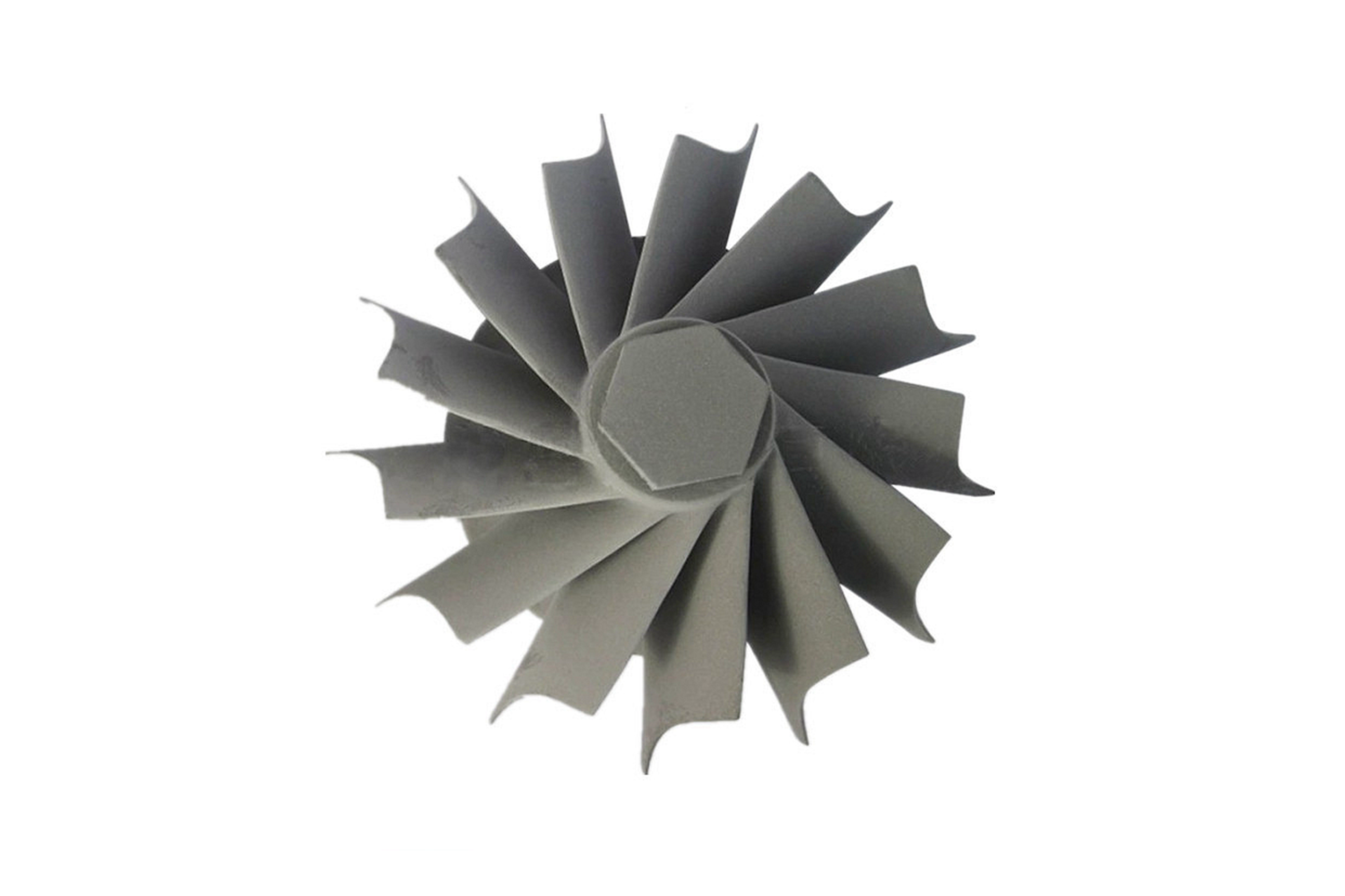
Les composants de turbocompresseur dans les moteurs aérospatiaux, les véhicules hautes performances et les turbines de production d'énergie fonctionnent sous des charges thermiques et mécaniques sévères. Les roues de turbine, les aubes et les tuyères rotatives sont constamment exposées à des gaz d'échappement à haute vitesse et à des températures élevées dépassant 1000°C. Ces conditions extrêmes exigent des matériaux résistants au fluage, à l'oxydation et à la fatigue. CMSX-4, un superalliage monocristallin à base de nickel de deuxième génération, est conçu pour offrir une haute résistance, une excellente résistance à l'oxydation et une stabilité thermique à long terme dans de tels environnements exigeants.
Neway AeroTech propose le moulage directionnel de composants de turbocompresseur en CMSX-4 en utilisant le moulage à la cire perdue sous vide et des sélecteurs de grains hélicoïdaux. Nos solutions fournissent des composants à grains colonnaires orientés [001] avec une durée de vie au fluage et une résistance à la fatigue supérieures pour les systèmes turbo aérospatiaux, automobiles et de production d'énergie.
Technologie de base du moulage directionnel CMSX-4 pour composants de turbocompresseur
Précision du modèle en cire Des modèles en cire haute fidélité sont créés pour les roues de turbine, les aubes directrices de tuyère et les carter diffuseurs avec une précision de ±0,05 mm.
Construction du moule en coquille Des coquilles céramiques multicouches (6–10 mm d'épaisseur) sont construites pour résister aux gradients thermiques de solidification directionnelle et aux températures de coulée de l'alliage.
Intégration du sélecteur de grains Des sélecteurs de grains hélicoïdaux ou de démarrage guident la croissance des grains colonnaires dans la direction [001], éliminant les joints de grains dans les sections critiques.
Fusion par induction sous vide Le CMSX-4 est fondu sous vide (≤10⁻³ Pa) à ~1450–1480°C, assurant une uniformité chimique et minimisant la formation d'inclusions.
Solidification directionnelle Les moules sont retirés à une vitesse de 2–4 mm/min sous un gradient thermique contrôlé, produisant des grains alignés avec une haute résistance au fluage.
Démoulage et nettoyage de surface Les coquilles céramiques sont retirées par grenaillage à haute pression et nettoyage chimique, préservant les caractéristiques de refroidissement précises et les épaisseurs de paroi.
Traitement thermique et HIP Le pressage isostatique à chaud (HIP) élimine la porosité, et les traitements de mise en solution et de vieillissement affinent la distribution de la phase γ′ pour des propriétés mécaniques supérieures.
Usinage CNC et EDM Les caractéristiques à tolérance serrée telles que les faces de fixation et les passages de refroidissement sont finies par usinage CNC et EDM.
Propriétés du matériau CMSX-4 pour composants de turbocompresseur
Température de fonctionnement maximale : ~1100°C
Résistance à la traction : ≥1100 MPa
Résistance à la rupture par fluage : ≥230 MPa à 982°C pendant 1000 heures
Fraction volumique de Gamma Prime : ~70%
Résistance à l'oxydation : Excellente sous flux de gaz chaud
Microstructure : Solidification directionnelle, grains colonnaires [001]
Étude de cas : Roues de turbine et tuyères CMSX-4 pour turbocompresseurs aérospatiaux
Contexte du projet
Neway AeroTech a fabriqué des roues de turbine et des anneaux de tuyère en CMSX-4 pour un turbocompresseur d'unité de puissance auxiliaire (APU) aérospatial fonctionnant à 1050°C. Le client exigeait des composants sans défaut avec une durée de vie au fluage prolongée et une stabilité dimensionnelle sous cyclage thermique extrême.
Applications
Rotors de turbine pour turbocompresseurs de moteurs à réaction Subissent des vitesses de rotation et des températures extrêmes, nécessitant une structure de grains résistante au fluage et à la fatigue.
Aubes directrices de tuyère pour le contrôle du flux de turbine Requièrent une excellente résistance à l'oxydation, une déformation minimale et l'élimination des joints de grains pour éviter la fissuration.
Diffuseurs et carter de turbo Structures statiques qui exigent des surfaces d'étanchéité serrées et une haute intégrité structurelle à températures élevées.
Flux de fabrication pour pièces de turbocompresseur CMSX-4
Optimisation CFD et du moule Des simulations CFD sont utilisées pour concevoir le système d'alimentation, les plaques de refroidissement et les sélecteurs afin d'optimiser la solidification directionnelle.
Moulage directionnel sous vide Le moulage est exécuté sous vide avec des vitesses de retrait contrôlées avec précision, obtenant un alignement directionnel des grains [001].
HIP et traitement thermique Le traitement HIP élimine toute porosité interne ; le traitement thermique stabilise les particules γ′ et améliore la résistance au fluage.
Finalisation par usinage CNC et EDM Les interfaces de précision, les faces d'étanchéité et les géométries de profil aérodynamique sont achevées via CNC et EDM.
Contrôle qualité et inspection L'orientation des grains et l'intégrité structurelle sont vérifiées à l'aide d'analyses rayons X, CMM et EBSD.
Défis de fabrication clés
Maintenir l'alignement des grains [001] à travers les sections courbes du rotor
Éviter la formation de grains parasites près des pieds d'aubes et des couronnes
Atteindre la stabilité dimensionnelle pendant les cycles de traitement thermique
Gérer le moulage de parois minces et le risque de porosité dans les segments de tuyère
Résultats et vérification
Orientation des grains [001] vérifiée par EBSD avec une déviation <2°
Structure sans porosité confirmée après HIP
Performance au fluage >230 MPa à 982°C validée par des essais mécaniques
Tolérances maintenues dans ±0,03 mm sur toutes les surfaces clés
Conformité 100% aux END sur tous les lots de production
FAQ
Quels sont les avantages du moulage directionnel CMSX-4 pour les turbocompresseurs ?
Comment la solidification directionnelle améliore-t-elle la durabilité des composants turbo ?
Quels types de pièces turbo peuvent être moulées en CMSX-4 ?
Comment l'orientation des grains [001] est-elle maintenue pendant le moulage ?
Les composants turbo CMSX-4 peuvent-ils être réparés ou reconditionnés ?
