एयरोस्पेस सुपरलॉय दहन कक्ष घटक एसएलएस 3डी प्रिंटिंग सेवा
एयरोस्पेस दहन घटकों के लिए एसएलएस 3डी प्रिंटिंग का परिचय
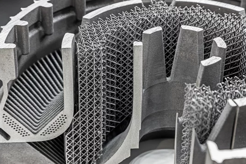
सेलेक्टिव लेजर सिंटरिंग (SLS) एयरोस्पेस-ग्रेड सुपरलॉय से जटिल दहन कक्ष घटकों के विनिर्माण के लिए एक विश्वसनीय विधि है। यह परत-दर-परत पाउडर फ्यूजन प्रक्रिया चरम ताप और दबाव के तहत जटिल ज्यामिति में समान घनत्व, नियंत्रित माइक्रोस्ट्रक्चर और तापीय अखंडता सुनिश्चित करती है।
Neway Aerotech में, हमारी एसएलएस 3डी प्रिंटिंग सेवाएं प्रणोदन प्रणालियों, एयरो इंजनों और टर्बाइन दहन असेंबली के लिए सुपरलॉय दहन भागों के निर्माण का समर्थन करती हैं।
एसएलएस 3डी प्रिंटिंग अवलोकन
प्रक्रिया क्षमताएं
पैरामीटर | मान |
|---|---|
परत की मोटाई | 40–60 μm |
न्यूनतम फीचर आकार | ~0.5 mm |
आयामी सहनशीलता | प्रति 100 मिमी ±0.1 मिमी |
अधिकतम कक्ष तापमान | सुपरलॉय निर्माण के लिए >1000°C |
घनत्व (HIP के बाद) | ≥99.7% |
एसएलएस एक ही बिल्ड चक्र में हल्की लैटिस संरचनाओं, आंतरिक शीतलन नेटवर्क और जटिल दीवार प्रोफाइल के निर्माण को सक्षम बनाता है।
एयरोस्पेस दहन कक्षों के लिए एसएलएस क्यों?
गैर-संपर्क परत फ्यूजन पतली-दीवार ज्यामिति को संरक्षित रखता है
जटिल फीचर्स (शीतलन छिद्र, लैटिस सुदृढ़ीकरण, एकीकृत पोर्ट) के एकीकरण का समर्थन करता है
उच्च-रिज़ॉल्यूशन पाउडर पिघलना 1000°C+ वातावरण में यांत्रिक प्रदर्शन सुनिश्चित करता है
HIP, EDM, और कोटिंग जैसे पोस्ट-प्रोसेसिंग के साथ पूरी तरह से संगत
सामग्री संबंधी विचार
एसएलएस दहन कक्षों के लिए सामान्य सुपरलॉय
सामग्री | अधिकतम तापमान (°C) | 800°C पर सामर्थ्य (MPa) | ऑक्सीकरण प्रतिरोध | आवेदन उपयोग मामला |
|---|---|---|---|---|
700–750 | ~970 | उत्कृष्ट | एयरो दस्तार लाइनर, ईंधन नोजल माउंट | |
>980 | ~1100 | श्रेष्ठ | टर्बाइन दहन कैन, स्विर्लर बॉडी | |
>1000 | ~1200 | उत्कृष्ट | बर्नर रिंग, इग्नाइटर हाउसिंग | |
~1175 | ~880 | असाधारण | ऑक्सीडाइजिंग गैस पथ में दहन दीवारें |
केस स्टडी: Inconel 939 दहन लाइनर खंड का एसएलएस विनिर्माण
परियोजना पृष्ठभूमि
एयरोस्पेस और विमानन क्षेत्र के एक ग्राहक को 3डी-प्रिंटेड आंतरिक शीतलन चैनलों, लैटिस स्टिफ्नर और एकीकृत ईंधन इनलेट वाले एक-टुकड़ा दहन लाइनर की आवश्यकता थी। चुनी गई सामग्री Inconel 939 थी, जो 980–1050°C संचालन तापमान के लिए उपयुक्त है।
विनिर्माण वर्कफ़्लो
एडिटिव के लिए डिज़ाइन: एकीकृत 1 मिमी शीतलन मार्ग, 0.7 मिमी लैटिस दीवारें, और अनुकूलित कक्ष कॉन्टूर
एसएलएस बिल्ड: परत की मोटाई 50 μm, बिल्ड समय 38 घंटे, आयामी सहनशीलता ±0.08 मिमी
HIP उपचार: 99.8% घनत्व तक पहुंचने के लिए 4 घंटे तक 1200°C, 100 MPa
EDM फिनिशिंग: ±0.005 मिमी सहनशीलता के साथ नोजल पोर्ट और सीलिंग फ्लैंज का स्पार्क इरोजन
कोटिंग: आंतरिक दीवारों पर थर्मल बैरियर कोटिंग लगाई गई
पोस्ट-प्रोसेसिंग और निरीक्षण
सभी कार्यात्मक फीचर्स का CMM सत्यापन
एक्स-रे निरीक्षण में कोई संकुचन या छिद्र क्लस्टर नहीं दिखा
SEM विश्लेषण ने समान ग्रेन फ्यूजन की पुष्टि की
अल्ट्रासोनिक इमर्शन टेस्टिंग ने आंतरिक अखंडता को सत्यापित किया
परिणाम और सत्यापन
अंतिम Inconel 939 दहन खंड ने ±0.08 मिमी के भीतर आयामी सटीकता प्राप्त की और सीलिंग क्षेत्रों पर Ra ≤ 0.6 μm समाप्त किया।
EDM परिष्करण के बाद सभी आंतरिक शीतलन पथ स्पष्ट थे, जिसमें मापी गई दीवार की मोटाई में भिन्नता ±0.05 मिमी से कम थी।
एक्स-रे और अल्ट्रासोनिक टेस्टिंग ने किसी भी सबसरफेस दोष या परत डेलामिनेशन के बिना >99.8% घनत्व की पुष्टि की।
भाग ने शून्य विरूपण या थकान दरार के साथ 1000-घंटे के उच्च-दबाव वाले गर्म गैस परीक्षण को सहन किया।
अक्सर पूछे जाने वाले प्रश्न
एसएलएस-प्रिंटेड दहन खंडों के लिए किस प्रकार के सुपरलॉय सबसे उपयुक्त हैं?
एसएलएस टर्बाइन दहन घटकों में सरंध्रता को कैसे संबोधित किया जाता है?
क्या फिल्म शीतलन चैनलों को सीधे मुद्रित किया जा सकता है और EDM का उपयोग करके पोस्ट-प्रोसेस किया जा सकता है?
एसएलएस दहन हार्डवेयर के लिए प्राप्त करने योग्य अधिकतम दीवार की मोटाई क्या है?
एसएलएस भागों के एयरोस्पेस प्रमाणन के लिए किस पोस्ट-ट्रीटमेंट की आवश्यकता है?
