Componentes de la Ruta de Gases Calientes Fundidos Direccionalmente en Superaleación Nimonic 75
Introducción
Los componentes de la ruta de gases calientes en turbinas de gas—como revestimientos de combustor, álabes de turbina, deflectores y conductos de transición de escape—están expuestos a condiciones operativas severas. Estas incluyen altas temperaturas, ciclos térmicos rápidos y oxidación por gases de combustión de alta velocidad. La selección del material es crítica para mantener la estabilidad dimensional y la resistencia a la fatiga térmica. Nimonic 75, una superaleación de níquel-cromo, ofrece una excelente resistencia a la oxidación y a la formación de escamas hasta 1000°C, lo que la convierte en un material adecuado para aplicaciones estructurales y de sección caliente.
Neway AeroTech fabrica componentes de la ruta de gases calientes en Nimonic 75 utilizando tecnología de fundición direccional, permitiendo estructuras de grano columnar que mejoran la vida a fluencia y reducen las fallas en los límites de grano. Combinado con fundición a la cera perdida al vacío, tratamiento térmico y mecanizado CNC, nuestras soluciones respaldan a los fabricantes de equipos originales (OEM) de turbinas para aeroespacial, generación de energía y marina.
Tecnología Central de la Fundición Direccional para Componentes de Nimonic 75
Ingeniería de Modelos de Cera Se crean modelos de cera de precisión para igualar geometrías complejas de perfiles aerodinámicos, álabes y transiciones con una tolerancia de ±0,05 mm.
Construcción del Molde de Cáscara Se forman moldes de cáscara cerámica multicapa (6–8 mm) para soportar altas temperaturas de fundición y una retirada controlada durante la solidificación.
Integración del Selector de Grano Se utilizan selectores de grano en espiral o bloques iniciadores para iniciar el crecimiento de grano [001], alineando los granos con la dirección principal de tensión.
Fusión por Inducción al Vacío El Nimonic 75 se funde al vacío (≤10⁻³ Pa) a ~1400°C para preservar la pureza y eliminar la porosidad por gas.
Solidificación Direccional El molde se retira de la zona de calor a 2–4 mm/min para formar granos columnares alineados a lo largo del eje de tensión para mejorar la resistencia a la fluencia.
Remoción y Limpieza de la Cáscara Las cáscaras cerámicas se eliminan mediante chorro de alta presión y lixiviación para preservar los detalles y evitar la distorsión de características delgadas.
Tratamiento Térmico El solución y recocido mejoran la ductilidad y estabilizan los límites de grano para un mejor rendimiento a la fatiga térmica.
Acabado CNC y EDM Las características del perfil aerodinámico, superficies de sellado e interfaces de pernos se finalizan utilizando mecanizado CNC y EDM.
Propiedades del Material Nimonic 75 en Forma Fundida Direccionalmente
Temperatura Máxima de Operación: ~1000°C
Resistencia a la Tracción: ≥830 MPa a 20°C
Límite Elástico: ≥485 MPa
Resistencia a la Fluencia: >100 MPa a 850°C durante 1000 hrs
Resistencia a la Oxidación y Formación de Escamas: Excelente en aire y gas a alta temperatura
Orientación del Grano: Estructura columnar [001] alineada direccionalmente (desviación <2°)
Estudio de Caso: Conductos de Transición y Álaves de Nimonic 75 Fundidos Direccionalmente
Antecedentes del Proyecto
Neway AeroTech fue seleccionada para fabricar segmentos de álabes de primera etapa y conductos de transición de gases calientes en Nimonic 75 para una turbina de gas industrial de 30 MW. Los componentes requerían alta resistencia a la fatiga térmica, estabilidad a la oxidación y estructura de grano columnar para soportar ciclos térmicos de hasta 950°C.
Aplicaciones
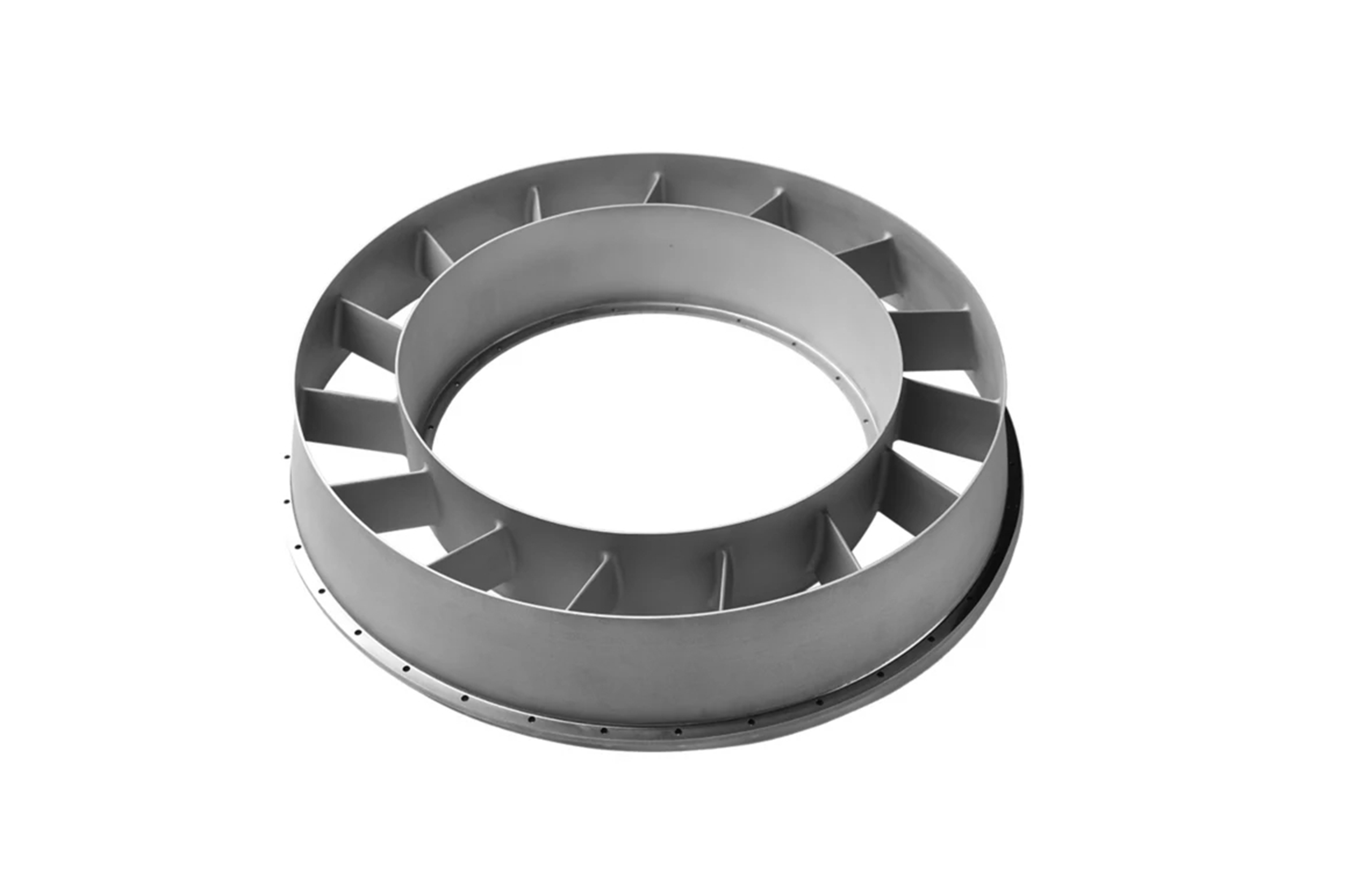
Álabes Guía de Tobera de Turbina Componentes estáticos de perfil aerodinámico que requieren estabilidad dimensional y baja distorsión por fluencia durante largos intervalos de servicio.
Conductos de Transición del Combustor Estructuras de pared delgada sometidas a oscilaciones de presión y choque térmico, que requieren alta vida a fatiga.
Anillos de Sello y Deflectores Soportan el sellado en zonas de combustión de alta velocidad; exigen resistencia a la erosión y control de los límites de grano.
Flujo de Trabajo de Fabricación para Componentes de Nimonic 75 Fundidos Direccionalmente
Diseño de Sistema de Alimentación Asistido por CFD La simulación CFD se utiliza para optimizar el sistema de alimentación, la forma del selector y las ubicaciones de enfriamiento para evitar puntos calientes y segregación.
Ejecución de la Fundición Direccional al Vacío La fundición se realiza en hornos de vacío con control de zona térmica y velocidades de retirada precisas para la alineación de grano [001].
Tratamiento Térmico Post-Fundición El recocido de solución mejora la ductilidad de los límites de grano y reduce las concentraciones de tensión interna.
Mecanizado e Inspección El EDM y el mecanizado CNC finalizan las características complejas, seguidas de inspección por CMM y rayos X para verificar la conformidad.
Desafíos Clave
Lograr el crecimiento de grano [001] en secciones curvas de pared delgada
Gestionar la protección contra la oxidación durante el enfriamiento post-fundición
Controlar la distorsión en vanos largos y no soportados de perfiles aerodinámicos
Asegurar una alineación de grano consistente en toda la producción por lotes
Resultados y Verificación
Granos direccionales [001] confirmados mediante EBSD con desviación <2°
Tamaño de grano ASTM 6 mantenido en toda la geometría de la fundición
Rendimiento a tracción y fluencia validado según estándares ASME
Tolerancia dimensional dentro de ±0,03 mm verificada mediante CMM de 5 ejes
100% de aprobación en ensayos no destructivos (NDT) en todos los lotes de producción
Preguntas Frecuentes (FAQs)
¿Cuáles son los beneficios de usar Nimonic 75 en componentes de la ruta de gases calientes?
¿Cómo mejora la fundición direccional la resistencia a la fluencia en los álabes de turbina?
¿Qué métodos de inspección verifican la alineación direccional del grano?
¿Se pueden reparar o soldar en campo los componentes de Nimonic 75?
¿Qué industrias utilizan componentes de turbina de Nimonic 75 fundidos direccionalmente?
