सुपरमिश्र धातु इनकोनेल 718 3D प्रिंटेड टर्बाइन ब्लेड उन्नत EDM विनिर्माण
3D प्रिंटेड इनकोनेल 718 टर्बाइन ब्लेड के लिए EDM फिनिशिंग का परिचय
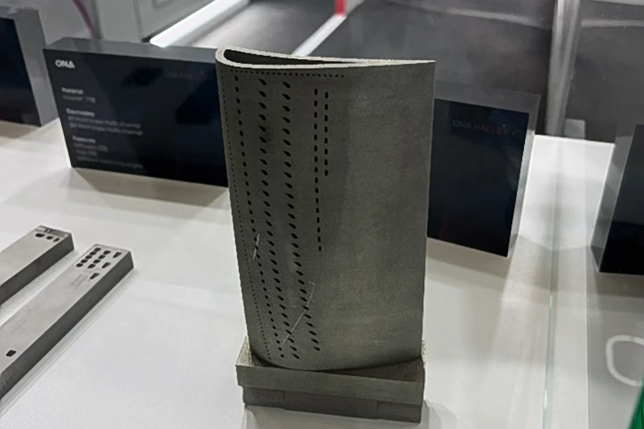
3D प्रिंटिंग के माध्यम से उत्पादित इनकोनेल 718 टर्बाइन ब्लेड को सटीक ज्यामिति और थर्मल थकान प्रतिरोध मानकों को पूरा करने के लिए उन्नत EDM फिनिशिंग की आवश्यकता होती है। इलेक्ट्रो-डिस्चार्ज मशीनिंग योगात्मक-विनिर्मित सुपरमिश्र धातु एयरफॉइल्स में माइक्रो-फीचर परिष्करण, आंतरिक गुहा पहुंच और अंतिम सहनशीलता नियंत्रण को सक्षम बनाती है।
Neway Aerotech में, हम बिजली उत्पादन और एयरोस्पेस प्रणोदन प्रणालियों के लिए उच्च-अखंडता वाले टर्बाइन ब्लेड प्रदान करने के लिए इनकोनेल 718 की 3D प्रिंटिंग को उन्नत EDM प्रसंस्करण के साथ जोड़ते हैं।
EDM मशीनिंग प्रौद्योगिकी अवलोकन
EDM मशीनिंग का वर्गीकरण
EDM प्रक्रिया | सतह खुरदरापन (Ra, μm) | आयामी सहनशीलता (mm) | पहलू अनुपात | ऊष्मा प्रभावित क्षेत्र (HAZ, μm) | न्यूनतम फीचर आकार (mm) |
|---|---|---|---|---|---|
वायर EDM | 0.3–1.2 | ±0.002–±0.01 | 20:1 तक | 2–5 μm | ~0.1 |
सिंकर EDM | 0.4–2.5 | ±0.005–±0.02 | 10:1 तक | 5–10 μm | ~0.2 |
होल ड्रिलिंग EDM | 0.5–3.0 | ±0.02–±0.05 | 30:1 तक | 10–15 μm | ~0.1 |
माइक्रो-EDM | 0.1–0.4 | ±0.001–±0.005 | 15:1 तक | <2 μm | <0.05 |
EDM योगात्मक विनिर्माण का पूरक है जो केवल लेजर फ्यूजन के माध्यम से असंभव अत्यंत बारीक फिनिश और जटिल गुहा ज्यामिति प्राप्त करता है।
EDM मशीनिंग चयन रणनीति
वायर EDM: एयरफॉइल किनारे की फिनिशिंग, टिप ट्रिमिंग और ट्रेलिंग एज परिभाषा के लिए आदर्श।
सिंकर EDM: रूट फॉर्म गुहाओं, अटैचमेंट ग्रूव्स और लॉकिंग फीचर्स के लिए उपयोग किया जाता है।
होल ड्रिलिंग EDM: आंतरिक फिल्म कूलिंग छिद्रों और निकास पोर्ट पर लागू होता है।
माइक्रो-EDM: गैस पथ क्षेत्रों में <0.2 mm ब्लीड होल और माइक्रो-नॉच को सक्षम बनाता है।
सामग्री संबंधी विचार
3D प्रिंटेड ब्लेड में इनकोनेल 718 के गुण
गुण | मान |
|---|---|
यील्ड स्ट्रेंथ @ 650°C | ~970 MPa |
कठोरता (HIP + एजिंग के बाद) | HRC 36–42 |
अधिकतम सेवा तापमान | 700–750°C |
ऑक्सीकरण प्रतिरोध | टर्बाइन वातावरण के लिए उत्कृष्ट |
3D प्रिंटिंग संगतता | SLM योगात्मक प्रक्रियाओं में सिद्ध |
3D प्रिंटेड इनकोनेल 718 ब्लेड के लिए EDM क्यों महत्वपूर्ण है
लैटिस और कूलिंग पास के अंदर सतह खुरदरापन को परिष्कृत करता है
अवशिष्ट पाउडर ट्रैप और रिकास्ट जोन को हटाता है
जटिल बाहरी फीचर्स का प्रिंट-पोस्ट अनुकूलन सक्षम बनाता है
HAZ को कम करता है और पतले खंडों में संरचनात्मक अखंडता को बनाए रखता है
केस स्टडी: In718 3D प्रिंटेड टर्बाइन ब्लेड का EDM पोस्ट-प्रोसेसिंग
परियोजना पृष्ठभूमि
बिजली उत्पादन उद्योग के एक ग्राहक को आंतरिक लैटिस संरचनाओं और 54 फिल्म कूलिंग छिद्रों वाली 3D प्रिंटेड इनकोनेल 718 टर्बाइन ब्लेड के लिए उच्च-सटीकता वाले पोस्ट-प्रोसेसिंग की आवश्यकता थी।
विनिर्माण कार्य प्रवाह
3D प्रिंटिंग: ब्लेड को परत दर परत बनाने के लिए SLM योगात्मक विनिर्माण का उपयोग किया गया, 40 μm मोटाई, घनत्व >99.7%
HIP उपचार: 4 घंटे के लिए 1200°C, 100 MPa पर हॉट आइसोस्टेटिक प्रेसिंग
वायर EDM: ±0.005 mm सटीकता के साथ किनारे ट्रिमिंग और टिप शेपिंग
होल EDM: 20:1 पहलू अनुपात पर फिल्म कूलिंग छिद्र (Ø0.6 mm) मशीन किए गए
सिंकर EDM: रूट अटैचमेंट पॉकेट गहराई 10 mm, सहनशीलता ±0.005 mm
पोस्ट प्रोसेस
2 घंटे के लिए 925°C पर तनाव-मुक्ति ऊष्मा उपचार
थकान जीवन को बढ़ाने के लिए शॉट पीनिंग (>25% सुधार)
EDM मलबे को हटाने और संक्षारण प्रतिरोध में सुधार करने के लिए अंतिम पैसिवेशन
सतह फिनिशिंग
फिल्म होल आउटलेट में आंतरिक सतहों को Ra ≤ 0.6 μm तक पॉलिश किया गया
एयरफॉइल टिप त्रिज्या को R0.05 mm तक नियंत्रित किया गया
SEM निरीक्षण के बाद कोई माइक्रोबर या दरार संकेतक नहीं
निरीक्षण
<2 μm विचलन के साथ 72 मुख्य बिंदुओं पर CMM
X-ray NDT ने आंतरिक चैनल अखंडता की पुष्टि की
अल्ट्रासोनिक इमर्शन टेस्टिंग ने पूर्ण छिद्र बंद होने को सत्यापित किया
फिल्म छिद्रों पर दबाव परीक्षण: 0.8 MPa वायु प्रवाह, सभी पोर्ट में <2% भिन्नता
परिणाम और सत्यापन
EDM फिनिशिंग ने जटिल 3D प्रिंटेड टर्बाइन ब्लेड प्रोफाइल में ±0.003 mm आयामी सटीकता और सुसंगत ज्यामिति प्रदान की।
सभी 54 फिल्म कूलिंग छिद्र प्रवाह समरूपता और Ra ≤ 0.6 μm आवश्यकता को पूरा करते हैं, जिससे अनुकूलित थर्मल प्रबंधन सक्षम हुआ।
SEM और CMM परिणामों से पता चला कि EDM पोस्ट-प्रोसेसिंग के बाद मूल CAD से कोई क्रैकिंग, विरूपण या आयामी विचलन नहीं हुआ।
अंतिम ब्लेड ने थकान-संबंधित विफलताओं के बिना 1000-घंटे के थर्मल सहनशीलता सिमुलेशन और >3000 ऑन-ऑफ चक्रों को पारित किया।
इस सफल पायलट के बाद ग्राहक ने सीरियल टर्बाइन ब्लेड उत्पादन के लिए EDM + 3D प्रिंट संयोजन को одобरित किया।
अक्सर पूछे जाने वाले प्रश्न (FAQs)
क्या EDM 3D प्रिंटेड टर्बाइन ब्लेड में आंतरिक कूलिंग पास को परिष्कृत कर सकता है?
धातु प्रिंटिंग के बाद EDM के साथ कौन सी आयामी सहनशीलताएं यथार्थवादी हैं?
क्या EDM लैटिस और सपोर्ट-फ्री ब्लेड संरचनाओं के साथ संगत है?
योगात्मक भागों में सतह थकान प्रतिरोध पर EDM का क्या प्रभाव पड़ता है?
प्रिंटेड In718 ब्लेड पर EDM के बाद आदर्श पोस्ट-प्रोसेसिंग चरण क्या हैं?
