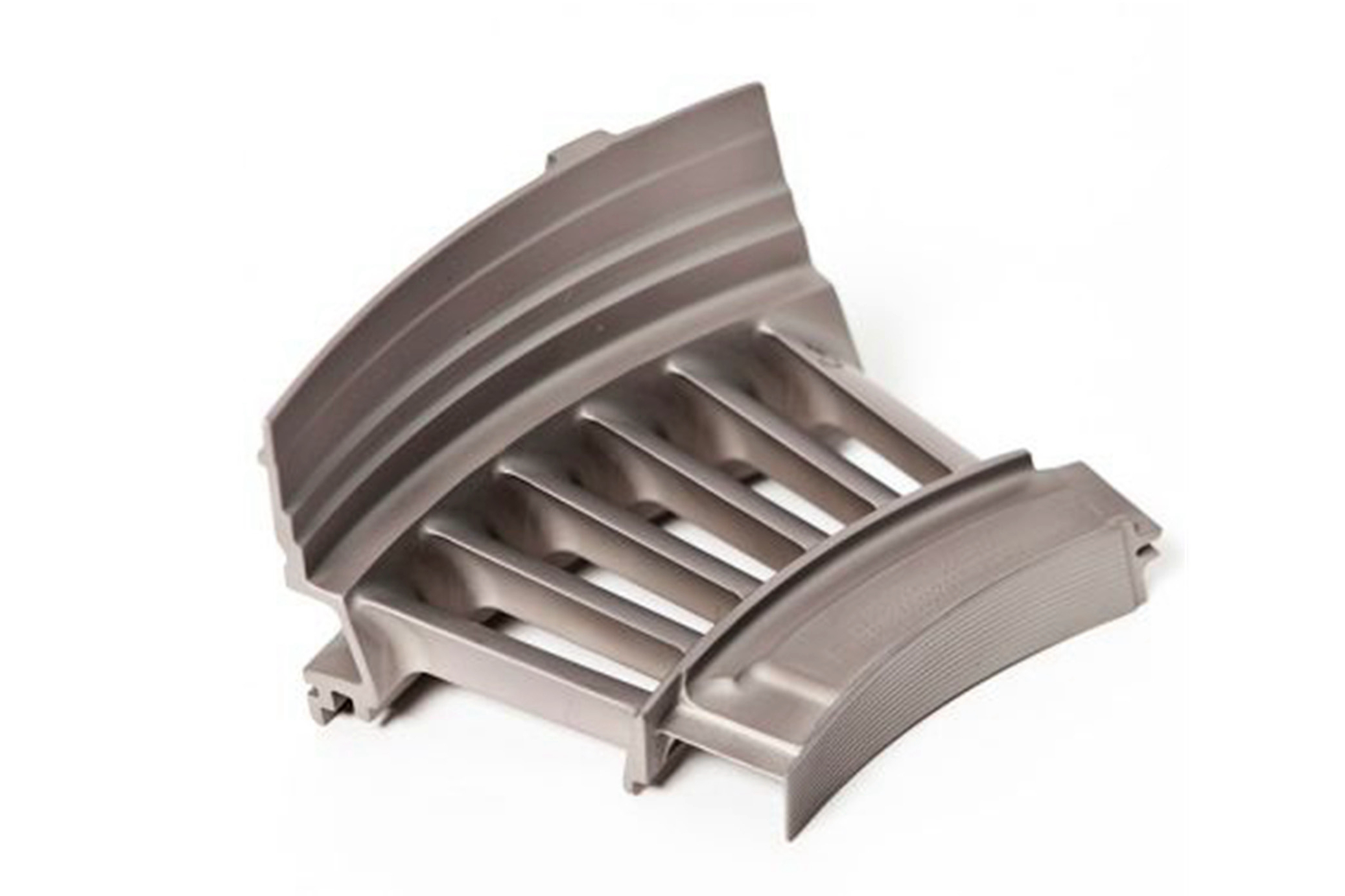
निमोनिक 80A सुपरएलॉय डायरेक्शनल कास्टिंग टरबाइन गाइड वेन
परिचय
गैस टरबाइन के प्रदर्शन में टरबाइन गाइड वेन्स की महत्वपूर्ण भूमिका होती है, जो उच्च तापमान वाली निकास गैसों के प्रवाह को घूमने वाले ब्लेड्स तक नियंत्रित करते हैं। इन घटकों को थर्मल फटीग, ऑक्सीकरण और निरंतर यांत्रिक तनाव का सामना करना पड़ता है। निमोनिक 80A, एक प्रेसिपिटेशन-स्ट्रेंथेंड निकल-आधारित सुपरएलॉय, अपने उत्कृष्ट उच्च-तापमान स्थिरता, ऑक्सीकरण प्रतिरोध और फटीग सामर्थ्य के कारण ऐसे अनुप्रयोगों के लिए उपयुक्त है।
जब डायरेक्शनल कास्टिंग का उपयोग करके निर्मित किया जाता है, तो निमोनिक 80A गाइड वेन्स को संरेखित स्तंभकार अनाज संरचनाओं से लाभ होता है, जिससे क्रीप लाइफ और थर्मल फटीग प्रतिरोध में सुधार होता है। न्यूवे एयरोटेक वैक्यूम इन्वेस्टमेंट कास्टिंग तकनीकों का उपयोग करके निमोनिक 80A वेन्स की डायरेक्शनल सॉलिडिफिकेशन तकनीकों का उपयोग करके वैक्यूम इन्वेस्टमेंट कास्टिंग प्रदान करता है, जो एयरोस्पेस, पावर जनरेशन, और मरीन गैस टरबाइनों की सेवा करता है।
निमोनिक 80A वेन्स के लिए डायरेक्शनल कास्टिंग की मुख्य तकनीक
वैक्स पैटर्न इंजेक्शन-मोल्डेड वैक्स पैटर्न ±0.05 मिमी के भीतर वेन ज्यामिति की प्रतिकृति बनाते हैं, जिसमें कूलिंग पैसेज और माउंटिंग इंटरफेस शामिल हैं।
सिरेमिक शेल मोल्ड बिल्डिंग 6–8 मिमी मोटी सिरेमिक शेल मोल्ड्स को परत-दर-परत बनाया जाता है ताकि वे डायरेक्शनल सॉलिडिफिकेशन तापमान और विथड्रॉल तनावों का सामना कर सकें।
ग्रेन सेलेक्टर इंटीग्रेशन मोल्ड असेंबली में पार्ट के नीचे एक सर्पिल ग्रेन सेलेक्टर रखा जाता है ताकि [001] स्तंभकार अनाजों के नियंत्रित विकास को सुनिश्चित किया जा सके।
वैक्यूम इंडक्शन मेल्टिंग निमोनिक 80A को वैक्यूम (≤10⁻³ Pa) में ~1380°C पर पिघलाया जाता है ताकि संदूषण को रोका जा सके और सुसंगत रसायन सुनिश्चित हो सके।
डायरेक्शनल सॉलिडिफिकेशन मोल्ड को धीरे-धीरे हीट ज़ोन (2–4 मिमी/मिनट) से बाहर निकाला जाता है, जिससे रूट से टिप तक एकदिशीय अनाज विकास को बढ़ावा मिलता है।
शेल नॉकआउट और सतह सफाई सॉलिडिफिकेशन के बाद, सिरेमिक मोल्ड को ब्लास्टिंग और लीचिंग के माध्यम से हटा दिया जाता है, जिससे एज फीचर्स और कूलिंग विवरण संरक्षित रहते हैं।
हॉट आइसोस्टेटिक प्रेसिंग (HIP) HIP 1150°C और 150 MPa पर माइक्रोपोरोसिटी को समाप्त करता है, जिससे फटीग और क्रीप प्रतिरोध बढ़ता है।
हीट ट्रीटमेंट सॉल्यूशन और एजिंग ट्रीटमेंट दीर्घकालिक संरचनात्मक स्थिरता और तनाव प्रतिरोध के लिए γ′ फेज वितरण को अनुकूलित करते हैं।
गाइड वेन्स के लिए निमोनिक 80A सामग्री गुण
अधिकतम ऑपरेटिंग तापमान: ~815°C
तन्यता शक्ति: कमरे के तापमान पर ≥1000 MPa
क्रीप प्रतिरोध: 750°C पर 1000 घंटे के लिए >150 MPa
फटीग सामर्थ्य: थर्मल साइक्लिंग के तहत उत्कृष्ट
ऑक्सीकरण प्रतिरोध: गैस टरबाइन वातावरण में मजबूत
अनाज संरचना: स्तंभकार, [001] दिशा में संरेखित
केस स्टडी: औद्योगिक टरबाइन के लिए डायरेक्शनल कास्ट निमोनिक 80A गाइड वेन्स
प्रोजेक्ट पृष्ठभूमि
न्यूवे एयरोटेक ने 90 MW पावर टरबाइन के लिए फर्स्ट-स्टेज गाइड वेन्स का निर्माण किया जो 800–820°C पर संचालित होती है। ग्राहक को कम-पोरोसिटी, डायरेक्शनली सॉलिडिफाइड निमोनिक 80A वेन्स की आवश्यकता थी जिनमें कड़े आयामी सहनशीलता और लंबी सेवा चक्रों पर विश्वसनीय ऑक्सीकरण प्रतिरोध हो।
विशिष्ट अनुप्रयोग
औद्योगिक गैस टरबाइन (जैसे, GE 6FA, Siemens SGT): फर्स्ट- और सेकेंड-स्टेज वेन्स जिन्हें उत्कृष्ट थर्मल फटीग प्रदर्शन और ऑक्सीकरण नियंत्रण की आवश्यकता होती है।
एयरोस्पेस इंजन (जैसे, टर्बोजेट्स, टर्बोफैन्स): हॉट गैस पाथ में गाइड वेन्स जो रैपिड स्टार्ट-स्टॉप थर्मल लोडिंग के संपर्क में आते हैं।
मरीन गैस टरबाइन (जैसे, LM2500): नमक-लदी निकास स्थितियों में क्षार- और गर्मी-प्रतिरोधी वेन संरचनाएं।
निमोनिक 80A वेन्स की डायरेक्शनल कास्टिंग के लिए निर्माण समाधान
वैक्स टूलिंग और मोल्ड डिजाइन वैक्स पैटर्न और CFD-अनुकूलित गेटिंग सिस्टम एकसमान धातु प्रवाह और नियंत्रित सॉलिडिफिकेशन सुनिश्चित करते हैं।
वैक्यूम कास्टिंग निष्पादन मोल्ड को वैक्यूम के तहत कास्ट किया जाता है और धीरे-धीरे डायरेक्शनल सॉलिडिफिकेशन के लिए बाहर निकाला जाता है, जिससे संरेखित स्तंभकार अनाज बनते हैं और लो-एंगल सीमाएं कम से कम होती हैं।
पोस्ट-कास्टिंग HIP और हीट ट्रीटमेंट पार्ट्स HIP और हीट ट्रीटमेंट से गुजरते हैं ताकि फेज स्थिरता और फटीग सामर्थ्य में सुधार हो सके।
प्रेसिजन मशीनिंग और EDM माउंटिंग सतहों, बॉसों और कूलिंग स्लॉट्स को CNC मशीनिंग और EDM का उपयोग करके पूरा किया जाता है।
निरीक्षण और सत्यापन मेटलोग्राफी, एक्स-रे परीक्षण, और CMM मापन डिजाइन विनिर्देशों के साथ पूर्ण अनुपालन सुनिश्चित करते हैं।
डायरेक्शनली कास्ट वेन्स के निर्माण में प्रमुख चुनौतियां
जटिल वेन ज्यामिति में सुसंगत [001] अनाज अभिविन्यास प्राप्त करना
पतली ट्रेलिंग एज और एयरफॉइल टिप्स में स्ट्रे ग्रेन से बचना
हॉट टीयर या विरूपण को रोकने के लिए थर्मल ग्रेडिएंट्स को नियंत्रित करना
आयामी सटीकता और कूलिंग पैसेज अखंडता को संतुलित करना
परिणाम और सत्यापन
[001] अभिविन्यास EBSD के माध्यम से पुष्टि के साथ <2° विचलन के साथ प्राप्त किया गया
पोरोसिटी-मुक्त सूक्ष्मसंरचना पोस्ट-HIP के बाद सत्यापित
750°C पर क्रीप सामर्थ्य >150 MPa सभी पार्ट्स में बनाए रखा गया
एयरफॉइल और प्लेटफॉर्म में ±0.03 मिमी के भीतर आयामी सटीकता
अल्ट्रासोनिक और एक्स-रे निरीक्षणों में 100% पास दर
अक्सर पूछे जाने वाले प्रश्न
टरबाइन गाइड वेन्स के लिए डायरेक्शनल कास्टिंग के क्या लाभ हैं?
गैस टरबाइन वेन अनुप्रयोगों के लिए निमोनिक 80A को क्यों चुना जाता है?
कास्टिंग के दौरान [001] अनाज अभिविन्यास कैसे सुनिश्चित किया जाता है?
वेन गुणवत्ता को सत्यापित करने के लिए किन निरीक्षण विधियों का उपयोग किया जाता है?
क्या डायरेक्शनल वेन्स दोनों औद्योगिक और एयरोस्पेस टरबाइनों के लिए उत्पादित किए जा सकते हैं?
