Empresa de Componentes Personalizados de Superaleación Nimonic para Cámaras de Combustión de Turbina...
Introducción a los Componentes Nimonic para Cámaras de Combustión de Turbinas de Gas
Las superaleaciones Nimonic, caracterizadas por una estabilidad térmica excepcional y una resistencia superior a la fluencia, son materiales ideales para componentes de cámaras de combustión de turbinas de gas. En Neway AeroTech, nos especializamos en la fabricación de componentes de aleación Nimonic de alta calidad adaptados específicamente para exigentes aplicaciones energéticas. Utilizando técnicas avanzadas de fundición a la cera perdida al vacío y solidificación direccional de precisión, entregamos componentes con una fiabilidad y durabilidad excepcionales.
Nuestra experiencia garantiza que los componentes Nimonic cumplan con criterios de rendimiento estrictos bajo las condiciones operativas extremas típicas de las turbinas de gas del sector energético.
Desafíos Principales de Fabricación para Componentes Nimonic
La fabricación de componentes Nimonic de alta temperatura presenta varios desafíos críticos:
Estabilidad Térmica: Mantener las propiedades mecánicas a temperaturas de operación superiores a 1000°C.
Resistencia a la Fluencia: Asegurar que los componentes resistan la deformación bajo tensión continua a temperaturas elevadas.
Corrosión y Oxidación: Proteger contra la corrosión a alta temperatura y los ambientes oxidativos.
Requisitos de Precisión: Lograr tolerancias dimensionales estrictas (±0,10 mm) para geometrías complejas.
Explicación Detallada de los Procesos de Fabricación
Fundición a la Cera Perdida al Vacío
Formación de modelos de cera de precisión que replican geometrías intrincadas del componente.
Creación de un molde de capa cerámica seguida de la eliminación de la cera a aproximadamente 180°C.
Colada de la aleación realizada bajo vacío (<0,01 Pa), minimizando impurezas y asegurando pureza metalúrgica.
Enfriamiento controlado (25–35°C/hora) para mitigar tensiones internas y mejorar la precisión dimensional.
Fundición por Solidificación Direccional
Gradientes térmicos controlados (20–50°C/cm) utilizados para alinear la estructura granular.
Mejora la resistencia a la fluencia y la vida a fatiga del componente mediante la alineación direccional del grano.
Velocidades de enfriamiento lentas (20–35°C/hora) para minimizar defectos internos y porosidad.
Comparación de los Principales Procesos de Fabricación
Proceso | Precisión Dimensional | Acabado Superficial | Eficiencia | Capacidad de Complejidad |
|---|---|---|---|---|
Fundición a la Cera Perdida al Vacío | ±0,15 mm | Ra 3,2–6,3 µm | Moderada | Alta |
Solidificación Direccional | ±0,20 mm | Ra 6,3–12,5 µm | Moderada | Moderada |
Mecanizado CNC | ±0,01 mm | Ra 0,8–3,2 µm | Moderada | Moderada |
Impresión 3D SLM | ±0,05 mm | Ra 6,3–12,5 µm | Alta | Muy Alta |
Estrategia de Selección de Proceso de Fabricación para Piezas Nimonic
Fundición a la Cera Perdida al Vacío: Recomendada para geometrías complejas y detalladas que requieren una precisión de alrededor de ±0,15 mm y alta calidad metalúrgica.
Fundición por Solidificación Direccional: Ideal para mejorar la resistencia a la fluencia y a la fatiga, adecuada para una precisión de ±0,20 mm.
Mecanizado CNC: Preferido para el acabado preciso de características críticas, logrando tolerancias dentro de ±0,01 mm.
Impresión 3D SLM: Excelente para prototipado rápido y estructuras internas complejas, ofreciendo una precisión de ±0,05 mm.
Matriz de Análisis de Materiales para Aleaciones Nimonic
Material | Resistencia a la Tracción (MPa) | Límite Elástico (MPa) | Temperatura Máx. de Operación (°C) | Resistencia a la Oxidación | Aplicaciones Típicas |
|---|---|---|---|---|---|
1160 | 815 | 920 | Superior | Álabes de turbina, discos | |
1050 | 585 | 815 | Excelente | Cámaras de combustión, elementos de fijación | |
1000 | 620 | 900 | Destacada | Revestimientos de combustor, conductos de escape | |
1200 | 880 | 950 | Excepcional | Componentes de turbina de alta presión | |
1065 | 750 | 820 | Superior | Segmentos de combustor, álabes directores de tobera | |
750 | 275 | 800 | Buena | Soportes estructurales, pantallas térmicas |
Estrategia de Selección de Material
Nimonic 90: Preferida para álabes y discos de turbina que requieren alta resistencia a la tracción (1160 MPa) y resistencia a la fluencia hasta 920°C.
Nimonic 80A: Óptima para cámaras de combustión y elementos de fijación debido a su excelente resistencia (1050 MPa a tracción) y resistencia a la oxidación a 815°C.
Nimonic 263: Ideal para revestimientos de combustor y conductos de escape, proporcionando un rendimiento robusto (1000 MPa a tracción) a temperaturas de 900°C.
Nimonic 105: Recomendada para componentes de turbina de alta presión que necesitan una resistencia excepcional (1200 MPa a tracción) y estabilidad a 950°C.
Nimonic PE16: Elegida para segmentos de combustor y álabes directores de tobera debido a sus propiedades mecánicas superiores (1065 MPa a tracción) a 820°C.
Nimonic 75: Adecuada para soportes estructurales y pantallas térmicas debido a su buena estabilidad térmica y rendimiento rentable a 800°C.
Tecnologías Clave de Postprocesado
Prensado Isostático en Caliente (HIP): Elimina la porosidad interna, mejorando sustancialmente el rendimiento a fatiga y fluencia a alrededor de 1200°C y 150 MPa.
Recubrimiento de Barrera Térmica (TBC): Reduce las temperaturas superficiales en aproximadamente 200°C, extendiendo significativamente la vida útil del componente.
Mecanizado por Descarga Eléctrica (EDM): Permite la fabricación precisa de geometrías internas complejas con una precisión de ±0,005 mm.
Tratamiento Térmico: Mejora la estabilidad microestructural, aumentando la resistencia y la resistencia a la corrosión.
Aplicación Industrial y Análisis de Caso
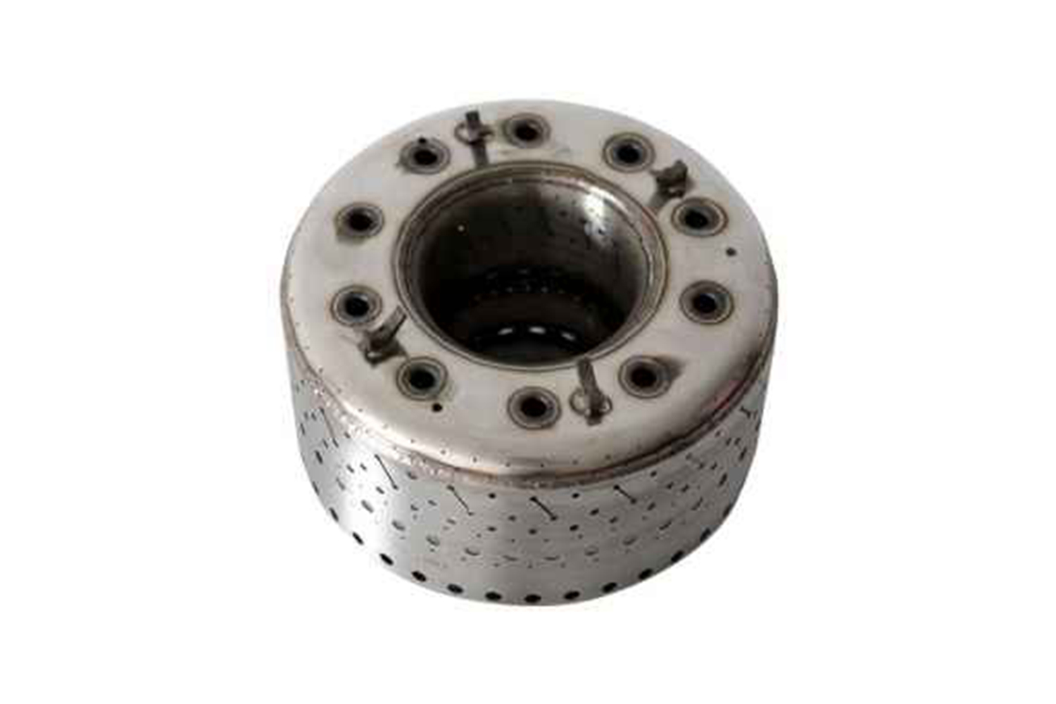
Neway AeroTech proporcionó componentes personalizados de cámara de combustión Nimonic 90 para un OEM energético global. Utilizando fundición a la cera perdida al vacío, HIP y TBC, logramos una precisión dimensional dentro de ±0,15 mm, una resistencia superior a la fluencia y una durabilidad excepcional, extendiendo significativamente la vida útil del componente bajo temperaturas operativas sostenidas de 920°C.
Nuestras capacidades integrales, control de calidad riguroso y profunda experiencia en materiales nos convierten en un socio de confianza para componentes Nimonic de alto rendimiento.
Preguntas Frecuentes
¿Qué plazos de entrega típicos pueden ofrecer para componentes personalizados de turbina Nimonic?
¿Puede su empresa manejar el prototipado y la producción de pequeños volúmenes de componentes Nimonic?
¿Con qué certificaciones de la industria cumplen sus piezas de superaleación Nimonic?
¿Qué técnicas de postprocesado mejoran mejor el rendimiento de las aleaciones Nimonic?
¿Proporcionan soporte técnico para la selección de aleaciones y la optimización del diseño de cámaras de combustión?
