Manufacturing Process for GE 9E 9171E Hot Gas Path Components: Casting, CNC Machining and TBC
Manufacturing Process for GE 9E / 9171E Hot Gas Path Components: Casting, HIP, CNC, EDM, Cooling Holes, and TBC
GE 9E / 9171E hot gas path components operate in one of the most demanding areas of an industrial gas turbine. Nozzles, buckets, guide vanes, shrouds, combustion liners, transition pieces, and heat shields are exposed to high temperature, oxidation, creep, vibration, erosion, and repeated thermal cycling. For these parts, the manufacturing process must control not only shape and size, but also alloy integrity, grain structure, cooling features, coating quality, and final inspection records.
NewayAeroTech supports custom manufacturing of GE 9E-type, 9171E-class, and E-class gas turbine hot gas path components through integrated superalloy manufacturing routes. Depending on the part type and service condition, we can combine Vacuum Investment Casting, Equiaxed Crystal Casting, Superalloy Directional Casting, Single Crystal Casting, HIP, heat treatment, CNC machining, EDM, deep hole drilling, TBC, welding, and final inspection.
This article explains the typical manufacturing route for GE 9E / 9171E hot gas path parts, including process selection, casting or forging, HIP, heat treatment, CNC machining, EDM cooling holes, coating, quality inspection, and quotation information required from buyers.
Step 1: Review the GE 9E / 9171E Part Function and Service Condition
The manufacturing process should start with the function of the part. A 1st stage nozzle, 1st stage bucket, 2nd stage bucket, shroud segment, combustion liner, and transition piece may all belong to the hot gas path, but they do not have the same stress, temperature, coating, cooling, and assembly requirements. Manufacturing the wrong process route can increase the risk of cracking, distortion, premature oxidation, coating failure, or poor assembly fit.
For GE 9E-type turbine parts, the engineering team should review the turbine model, part stage, material grade, operating temperature, gas path exposure, load direction, cooling structure, coating requirement, and inspection level. This review determines whether the part should be cast, forged, machined from billet, manufactured by additive processes, or produced using a hybrid route.
Engineering Input | Why It Matters | Impact on Manufacturing Route |
|---|---|---|
Turbine model | Confirms whether the part is for GE 9E, 9171E, or another E-class platform | Helps define dimensional envelope, application, and replacement manufacturing requirement |
Part stage | Different stages face different temperature and stress levels | Influences material, grain structure, coating, and inspection level |
Material grade | Determines casting, forging, heat treatment, machining, and coating compatibility | Controls process feasibility and quality risks |
Cooling features | Cooling holes and internal passages are critical for hot gas path reliability | May require EDM, deep hole drilling, CT inspection, or flow verification |
Coating requirement | TBC, MCrAlY, Al-Si, or oxidation-resistant coatings affect surface allowance | Must be considered before final machining and inspection planning |
Step 2: Select the Superalloy Manufacturing Route
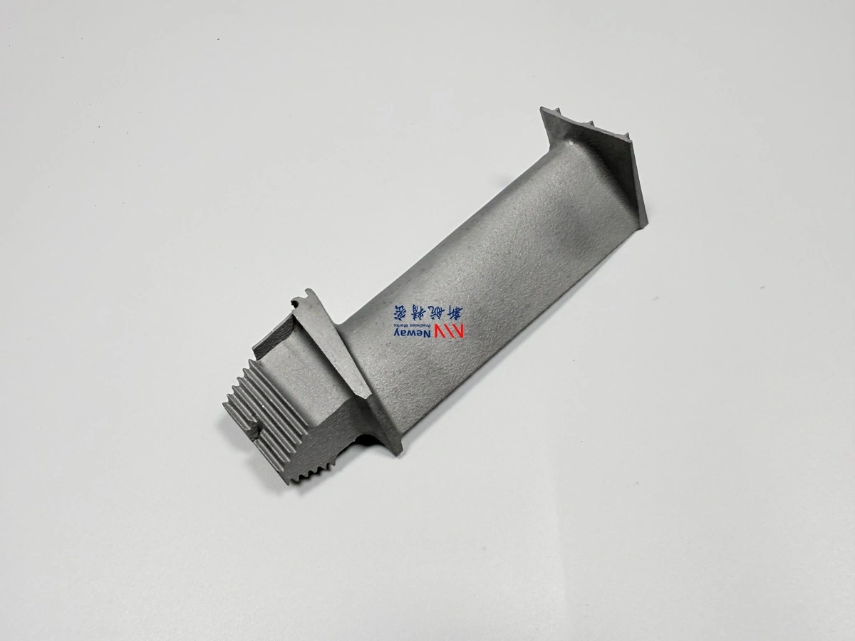
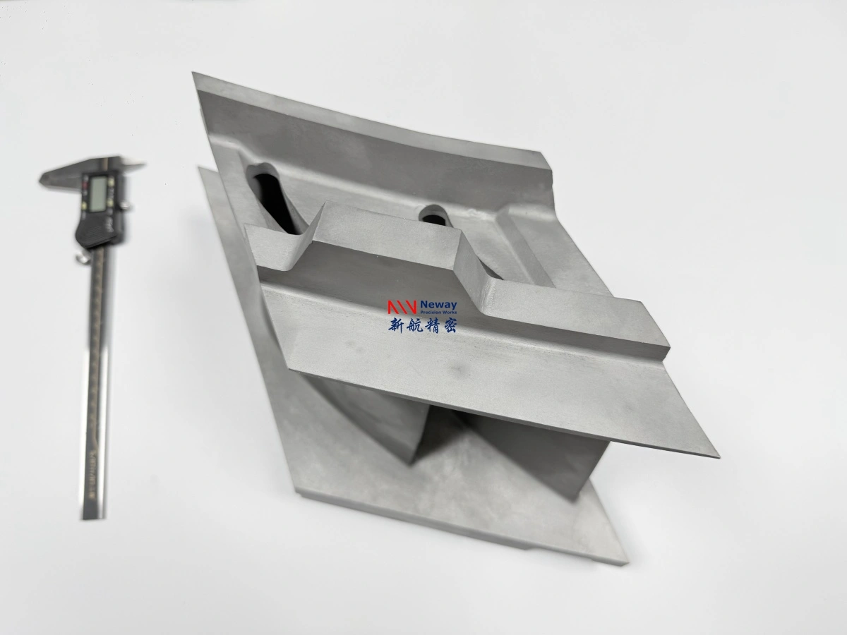
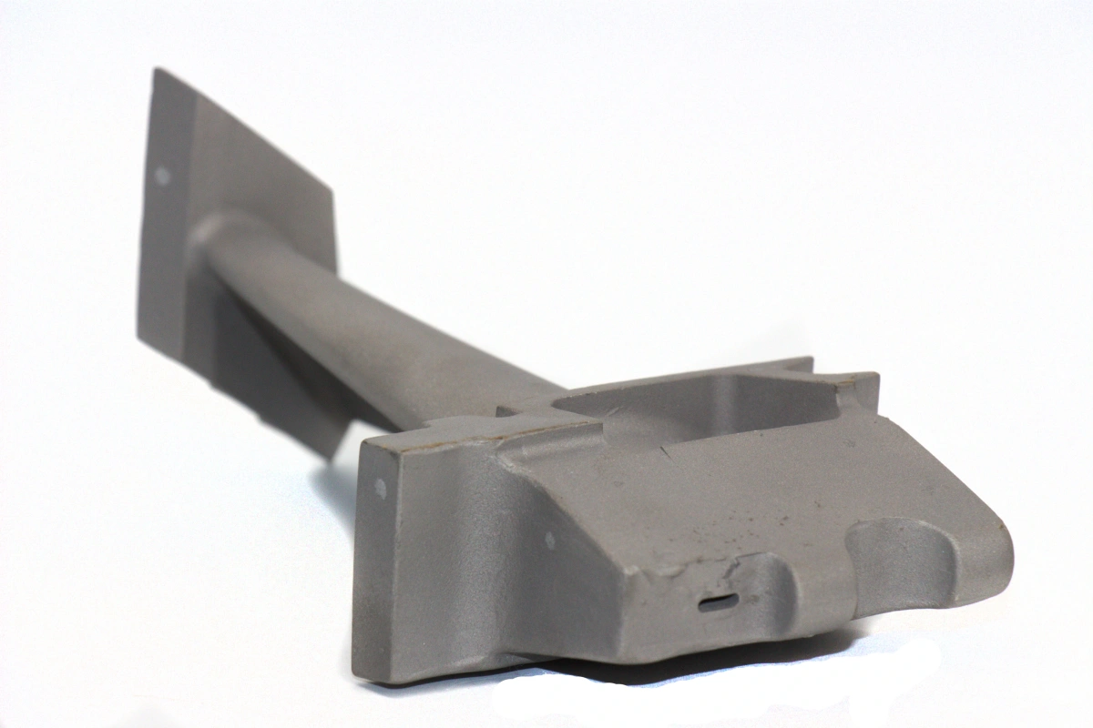
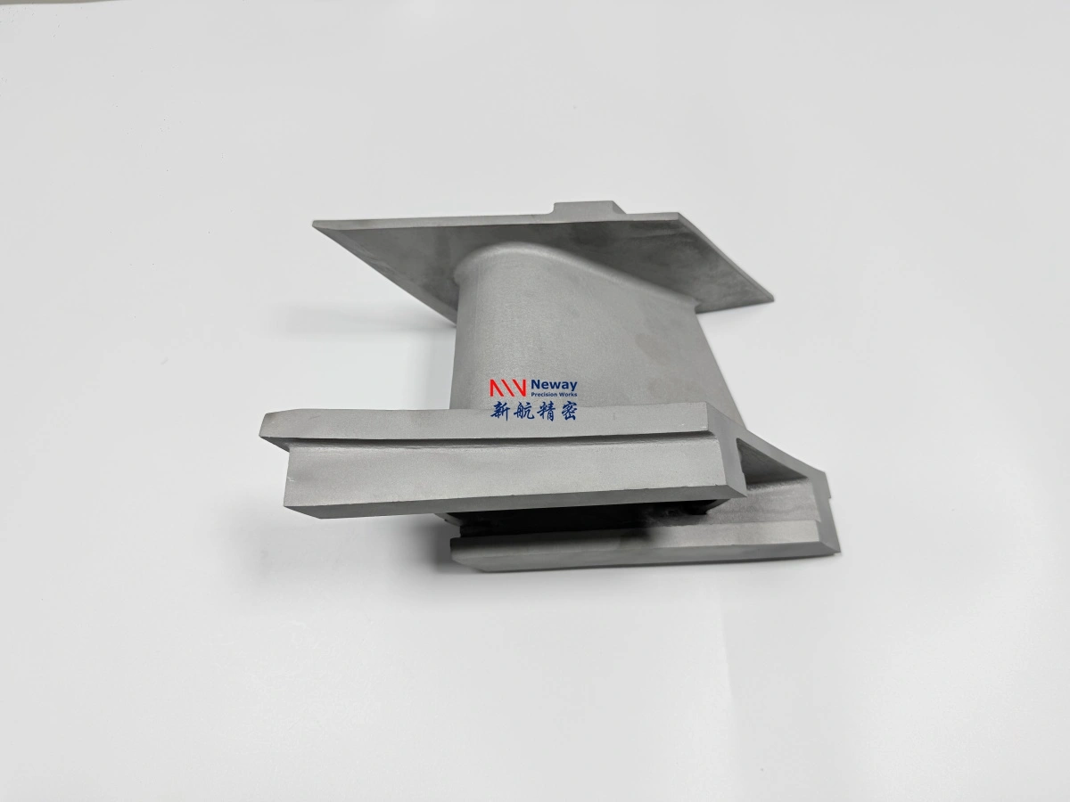
GE 9E / 9171E hot gas path components can be manufactured using different processes depending on geometry and service conditions. Nozzles and guide vanes are often produced by investment casting because they have complex airfoil profiles and integrated platforms. Buckets and blades may require equiaxed, directional, or single crystal casting depending on stage and creep requirements. Rotor-related or disc-type components may require forging or powder metallurgy instead of conventional casting.
NewayAeroTech supports Casting Superalloys, Superalloy Precision Forging, and Powder Metallurgy Turbine Disc manufacturing for different turbine component types. The correct route should be selected before tooling, machining allowance, heat treatment, coating, and inspection planning begin.
Component Type | Common Process Route | Manufacturing Reason |
|---|---|---|
1st Stage Nozzle | Vacuum investment casting + heat treatment + coating + CNC finishing | Supports complex airfoil geometry, high-temperature alloy casting, and gas path surface control |
1st Stage Bucket / Blade | Directional or single crystal casting + HIP + heat treatment + EDM + TBC | Improves creep performance, fatigue resistance, and cooling feature reliability |
2nd Stage Nozzle | Equiaxed or directional casting + CNC machining + protective coating | Balances hot gas path performance, dimensional control, and production cost |
2nd / 3rd Stage Bucket | Superalloy casting + shroud machining + hardface welding + inspection | Controls root fit, scalloped tip shroud, Z-notch areas, and wear-resistant features |
Turbine Disc / Rotor-Related Part | Precision forging or powder metallurgy + heat treatment + CNC machining | Supports high-stress rotating applications requiring strength and structural integrity |
Step 3: Create the Casting or Forging Blank
The blank manufacturing stage determines the foundation of final part quality. For cast nozzles, vanes, and buckets, mold design, wax pattern accuracy, shell quality, alloy melting, pouring control, solidification, grain structure, and cooling rate all affect final performance. For forged or powder metallurgy parts, billet quality, deformation control, temperature, pressure, and heat treatment history affect mechanical properties.
For GE 9E / 9171E hot section castings, vacuum melting and controlled casting are important because high-temperature superalloys are sensitive to oxidation, contamination, shrinkage, and microstructural variation. The casting route must consider wall thickness, airfoil shape, platform features, shrinkage allowance, core removal, and later CNC machining datum.
Blank Manufacturing Factor | Control Objective | Typical Risk If Not Controlled |
|---|---|---|
Wax pattern accuracy | Maintains airfoil, platform, root, and shroud geometry before casting | Profile deviation, poor machining allowance, assembly mismatch |
Ceramic shell quality | Supports surface finish, dimensional stability, and defect reduction | Surface defects, shell inclusion, dimensional distortion |
Vacuum melting and pouring | Reduces oxidation and improves alloy cleanliness | Inclusions, chemistry deviation, oxide defects |
Solidification control | Controls grain structure, shrinkage, and internal quality | Porosity, hot tearing, stray grains, low creep performance |
Machining allowance | Ensures enough stock for final root, platform, and interface machining | Insufficient cleanup, fixture instability, tolerance failure |
Step 4: Apply HIP and Heat Treatment for Superalloy Integrity
After casting, GE 9E / 9171E hot gas path components often require post-processing to improve internal integrity and mechanical performance. Hot Isostatic Pressing (HIP) is used to reduce internal porosity and improve density in critical superalloy castings. This is especially important for parts exposed to thermal fatigue, creep, and cyclic loading.
Heat Treatment is used to optimize microstructure, stabilize dimensions, improve strength, and prepare the alloy for service. For nickel-based superalloys, heat treatment parameters influence precipitate distribution, creep resistance, fatigue behavior, and long-term thermal stability. Heat treatment should be selected according to the alloy grade, casting structure, part function, and customer specification.
Post Process | Purpose | Typical GE 9E-Type Parts |
|---|---|---|
HIP | Reduces internal porosity and improves casting density | Turbine buckets, blades, nozzles, guide vanes, shrouds |
Solution heat treatment | Homogenizes the alloy and prepares the microstructure | Inconel, Rene, CMSX, Nimonic, and other nickel-based superalloy parts |
Aging treatment | Develops final strength and high-temperature properties | Turbine blades, buckets, vanes, high-strength hot-section components |
Stress relief | Reduces residual stress before or after machining | Machined castings, welded components, precision hot-section parts |
Step 5: CNC Machining of Root, Platform, Shroud, and Sealing Surfaces
Most cast GE 9E / 9171E hot gas path components require CNC machining after casting and heat treatment. Nozzle mounting surfaces, bucket roots, blade platforms, shroud features, sealing faces, bolt holes, datum surfaces, and contact areas must be machined to meet assembly and inspection requirements. As-cast accuracy is not usually enough for critical interfaces.
NewayAeroTech provides Superalloy CNC Machining for high-temperature castings and forged components. For gas turbine parts, machining must be planned together with casting allowance and inspection datum. A poor datum strategy can cause geometry shift between the cast airfoil, machined root, and final assembly surfaces.
Machined Area | Manufacturing Purpose | Inspection Focus |
|---|---|---|
Bucket root | Ensures secure fit into the rotor slot | Profile tolerance, surface finish, contact area, datum relationship |
Blade platform | Controls gas path boundary and assembly interface | Flatness, parallelism, contour accuracy, machining allowance |
Nozzle mounting face | Controls nozzle fit, stage alignment, and sealing | Datum position, bolt hole accuracy, sealing surface finish |
Scalloped tip shroud | Improves tip-area geometry and contact behavior | Shroud profile, wear zone, Z-notch interface, local thickness |
Sealing surfaces | Reduces leakage and improves assembly reliability | Surface roughness, coating allowance, dimensional consistency |
Step 6: EDM and Deep Hole Drilling for Cooling Holes and Internal Passages
Cooling holes are one of the most important manufacturing features on turbine buckets, blades, nozzles, and vanes. These features help manage metal temperature during high-temperature gas turbine operation. For GE 9E-class hot section components, cooling hole geometry may include angled holes, film cooling holes, turbulated cooling features, internal channels, and narrow slots.
Because nickel-based superalloys are difficult to machine, conventional drilling may not be suitable for all cooling features. Electrical Discharge Machining (EDM) can produce small holes, complex slots, and difficult internal features in hard superalloys. Superalloy Deep Hole Drilling can be used for long, straight internal passages when the part geometry allows.
Cooling or Internal Feature | Manufacturing Process | Quality Risk to Control |
|---|---|---|
Film cooling holes | EDM drilling or laser drilling depending on geometry | Hole diameter, angle, burr, recast layer, flow consistency |
Turbulated cooling holes | EDM and controlled drilling process | Internal feature repeatability, blockage, cleaning difficulty |
Deep internal channels | Deep hole drilling or EDM according to depth and access | Straightness, wall breakthrough, internal surface quality |
Narrow slots | Wire EDM or sinker EDM | Slot width, edge condition, heat-affected layer |
Blocked or hidden passages | Machining plus CT or flow verification when required | Internal blockage, trapped material, inconsistent cooling performance |
Step 7: TBC, MCrAlY, Al-Si, and Wear-Resistant Surface Treatment
Surface protection is critical for GE 9E / 9171E hot gas path components. The coating system must be selected according to the alloy, temperature zone, gas path exposure, oxidation risk, and wear condition. For high-temperature airfoil surfaces, Thermal Barrier Coating (TBC) can help reduce thermal exposure to the base metal. MCrAlY bond coats can improve oxidation resistance and support ceramic coating adhesion.
For selected nozzles and vanes, Al-Si protective coating or other oxidation-resistant surface systems may be used. For shrouds, Z-notch regions, sealing faces, and wear-contact areas, Superalloy Welding or hardface processing may be required to improve wear resistance. Coating thickness and hardface allowance should be considered before final machining and inspection.
Surface Treatment | Typical Use | Control Requirement |
|---|---|---|
TBC | 1st stage buckets, turbine blades, nozzles, vanes, heat shields | Coating thickness, adhesion, coverage, thermal cycling behavior |
MCrAlY bond coat | Bond layer for TBC-coated hot gas path components | Surface preparation, oxidation resistance, ceramic coating compatibility |
Al-Si coating | Selected nozzles, vanes, and oxidation-sensitive surfaces | Uniform coverage, substrate compatibility, final inspection |
Hardface welding | Z-notch areas, shroud contact surfaces, sealing wear zones | Crack control, bonding quality, final machining, surface inspection |
Oxidation-resistant coating | Combustion liners, transition pieces, hot-section structures | Temperature capability, cyclic durability, coating integrity |
Step 8: Final Inspection and Quality Documentation
Final inspection confirms whether the GE 9E / 9171E hot gas path component meets drawing, material, dimensional, surface, coating, and documentation requirements. For superalloy nozzles, buckets, vanes, and shrouds, inspection should include both manufacturing verification and service-risk evaluation. It is not enough to check only the outside shape.
NewayAeroTech provides Material Testing and Analysis for high-temperature alloy parts. Depending on customer requirements, reports can include CMM inspection, 3D scan comparison, X-ray inspection, CT inspection, FPI, metallographic analysis, SEM/EDS, chemical composition verification, GDMS, ICP-OES, carbon sulfur analysis, tensile testing, coating thickness measurement, and final visual inspection.
Inspection Item | Typical Method | Purpose |
|---|---|---|
Dimensional accuracy | CMM inspection, 3D scanning | Verifies root, platform, airfoil, shroud, mounting, and sealing features |
Internal defects | X-ray, CT, ultrasonic inspection | Detects porosity, shrinkage, cracks, inclusions, and blocked internal features |
Surface cracks | FPI or dye penetrant inspection | Finds open surface cracks after casting, welding, heat treatment, or machining |
Material chemistry | Spectrometer, GDMS, ICP-OES, carbon sulfur analysis | Confirms alloy grade and critical element control |
Microstructure | Metallography, SEM/EDS, EBSD when required | Evaluates grain condition, phases, heat treatment result, and defect morphology |
Coating quality | Thickness inspection, adhesion review, visual inspection, surface roughness | Confirms TBC, bond coat, Al-Si, or hardface surface meets specification |
Process Route Example for GE 9E / 9171E Turbine Nozzles and Buckets
A typical GE 9E-class turbine nozzle manufacturing project may start from a 3D CAD model, 2D drawing, or reverse-engineered sample. The process can include wax pattern tooling, vacuum investment casting, heat treatment, CNC machining of mounting surfaces, protective coating, dimensional inspection, and final documentation. If the nozzle includes internal features or strict airfoil profile requirements, CT inspection or 3D scanning may be added.
A turbine bucket or blade project may require more advanced control. Depending on stage and material, the route may include directional casting or single crystal casting, HIP, heat treatment, root machining, EDM cooling holes, TBC coating, shroud machining, hardface welding, FPI, CMM inspection, and coating inspection. The route should be customized based on the actual part specification rather than copied from another component.
Example Part | Possible Route | Main Manufacturing Risk |
|---|---|---|
1st Stage Nozzle | Vacuum investment casting → heat treatment → CNC mounting faces → coating → CMM / CT inspection | Airfoil profile deviation, internal defects, coating inconsistency |
1st Stage Bucket | Directional or single crystal casting → HIP → heat treatment → root machining → EDM cooling holes → TBC → inspection | Creep resistance, cooling hole accuracy, root fit, coating adhesion |
2nd Stage Bucket | Superalloy casting → heat treatment → shroud machining → Z-notch hardface → FPI → dimensional inspection | Shroud geometry, wear surface cracking, root and platform tolerance |
Combustion Liner | High-temperature alloy forming or fabrication → welding → heat treatment → coating → inspection | Weld integrity, thermal fatigue, oxidation, distortion |
Reverse Engineering Support for Legacy GE 9E / 9171E Components
Some GE 9E / 9171E replacement part projects start with worn samples or incomplete drawings. In this situation, reverse engineering may be required before manufacturing. However, reverse engineering a gas turbine hot section part is not only a scanning task. Worn areas must be distinguished from original geometry, functional surfaces must be identified, and material, heat treatment, coating, and inspection requirements must be reconstructed or confirmed.
For hot gas path components, reverse engineering should include sample inspection, 3D scanning, material verification, functional surface analysis, machining datum planning, coating review, and manufacturability assessment. For parts with cooling holes, airfoils, shrouds, Z-notch features, or coated surfaces, engineering review before tooling can reduce production risk and improve final assembly fit.
Reverse Engineering Step | Purpose | Manufacturing Benefit |
|---|---|---|
Sample cleaning and visual review | Identify wear, cracks, coating damage, and functional areas | Prevents worn geometry from being copied directly |
3D scanning | Captures airfoil, root, shroud, and interface geometry | Supports CAD reconstruction and dimensional comparison |
Material verification | Confirms alloy family and chemistry direction | Helps select casting, heat treatment, coating, and inspection route |
Datum reconstruction | Defines how the part should be machined and inspected | Improves assembly fit and avoids geometry shift |
DFM review | Evaluates casting, machining, cooling holes, coating, and inspection feasibility | Reduces tooling changes, machining failure, and delivery risk |
What Information Is Needed to Quote GE 9E / 9171E Hot Gas Path Components?
To quote GE 9E / 9171E hot gas path components accurately, the supplier must understand the component function, turbine frame, material requirement, geometry, process route, post-processing, coating, inspection level, and delivery schedule. A turbine bucket with cooling holes and TBC coating requires a different quotation structure from a static nozzle, shroud segment, or combustion liner.
For faster quotation, please provide the following information:
Turbine model or application, such as GE 9E, 9171E, E-class gas turbine, or equivalent platform
Part name and stage, such as 1st stage nozzle, 1st stage bucket, 2nd stage nozzle, 3rd stage bucket, shroud, combustion liner, transition piece, or heat shield
3D CAD model, preferably STEP, X_T, IGS, or another editable format
2D drawing with tolerances, datum requirements, cooling hole notes, coating requirements, and inspection standards
Required material grade, such as Inconel 713C, Inconel 738LC, CMSX-4, Rene N5, Nimonic 90, Stellite 6B, Hastelloy X, or another superalloy
Required manufacturing route, such as vacuum investment casting, equiaxed casting, directional casting, single crystal casting, precision forging, powder metallurgy, CNC machining, EDM, or deep hole drilling
Required post-processing, such as HIP, heat treatment, TBC, MCrAlY bond coat, Al-Si coating, hardface welding, oxidation-resistant coating, or surface finishing
Inspection requirements, such as CMM report, FAI, X-ray, CT, FPI, metallography, SEM, chemical analysis, tensile testing, coating inspection, or flow verification
Quantity for prototype validation, outage spare parts, replacement manufacturing, or repeat production order
Target delivery schedule and shipping destination
Why NewayAeroTech for GE 9E / 9171E Hot Gas Path Component Manufacturing?
Manufacturing GE 9E / 9171E hot gas path components requires an integrated process chain. A successful nozzle, bucket, vane, shroud, or combustion component depends on superalloy selection, casting quality, HIP, heat treatment, CNC datum control, EDM cooling hole accuracy, coating performance, and inspection documentation. If these steps are handled separately without engineering coordination, dimensional and metallurgical risks can increase.
NewayAeroTech supports high-temperature alloy component manufacturing from process planning to final inspection. We can help evaluate material selection, casting method, post-processing, machining allowance, cooling hole manufacturing, coating strategy, and quality reports according to customer drawings, samples, specifications, and application requirements. Our capabilities support power generation, aerospace, energy, marine, oil and gas, and other high-temperature industrial applications.
GE 9E and 9171E names are used only to describe turbine-frame application requirements. NewayAeroTech focuses on custom manufacturing of superalloy components according to customer-provided drawings, samples, specifications, and project requirements.
FAQ
What GE 9E / 9171E gas turbine parts can be custom manufactured from superalloys?
Which manufacturing process is suitable for GE 9E turbine nozzles, buckets, and vanes?
How are cooling holes, coating surfaces, and wear areas manufactured on GE 9E turbine buckets?
What inspection reports are needed for GE 9E / 9171E replacement hot section components?