How are cooling holes, coating surfaces, and wear areas manufactured on GE 9E turbine buckets?
How Are Cooling Holes, Coating Surfaces, and Wear Areas Manufactured on GE 9E Turbine Buckets?
Cooling holes, coating surfaces, and wear areas on GE 9E turbine buckets are manufactured through a controlled combination of superalloy casting, HIP, heat treatment, CNC machining, EDM drilling, deep hole drilling, thermal barrier coating, MCrAlY bond coat, hardface welding, and final inspection. These features are critical because turbine buckets operate under high temperature, centrifugal load, oxidation, vibration, and repeated thermal cycling.
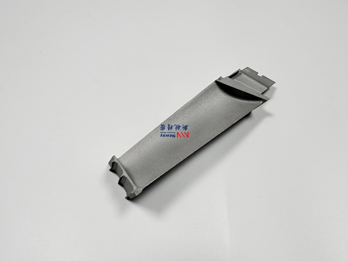
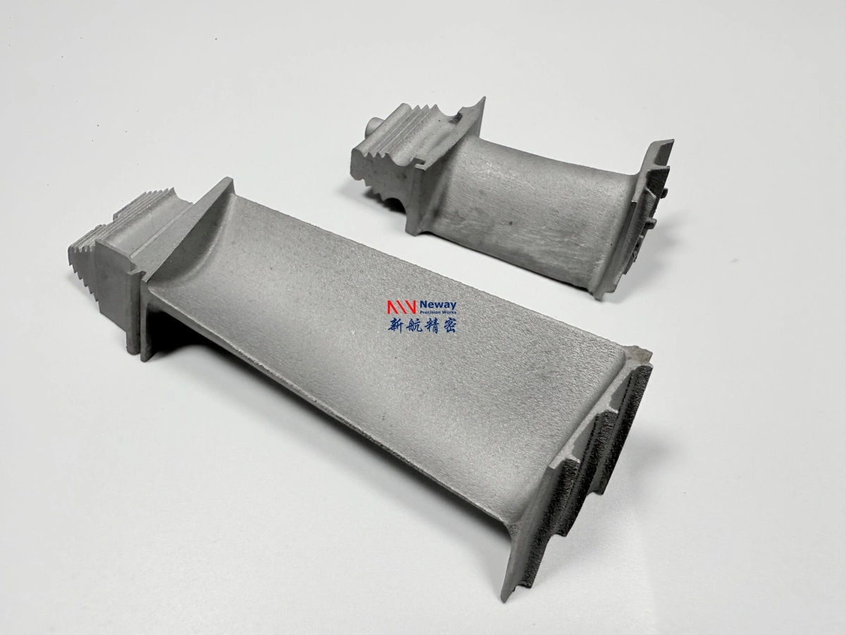
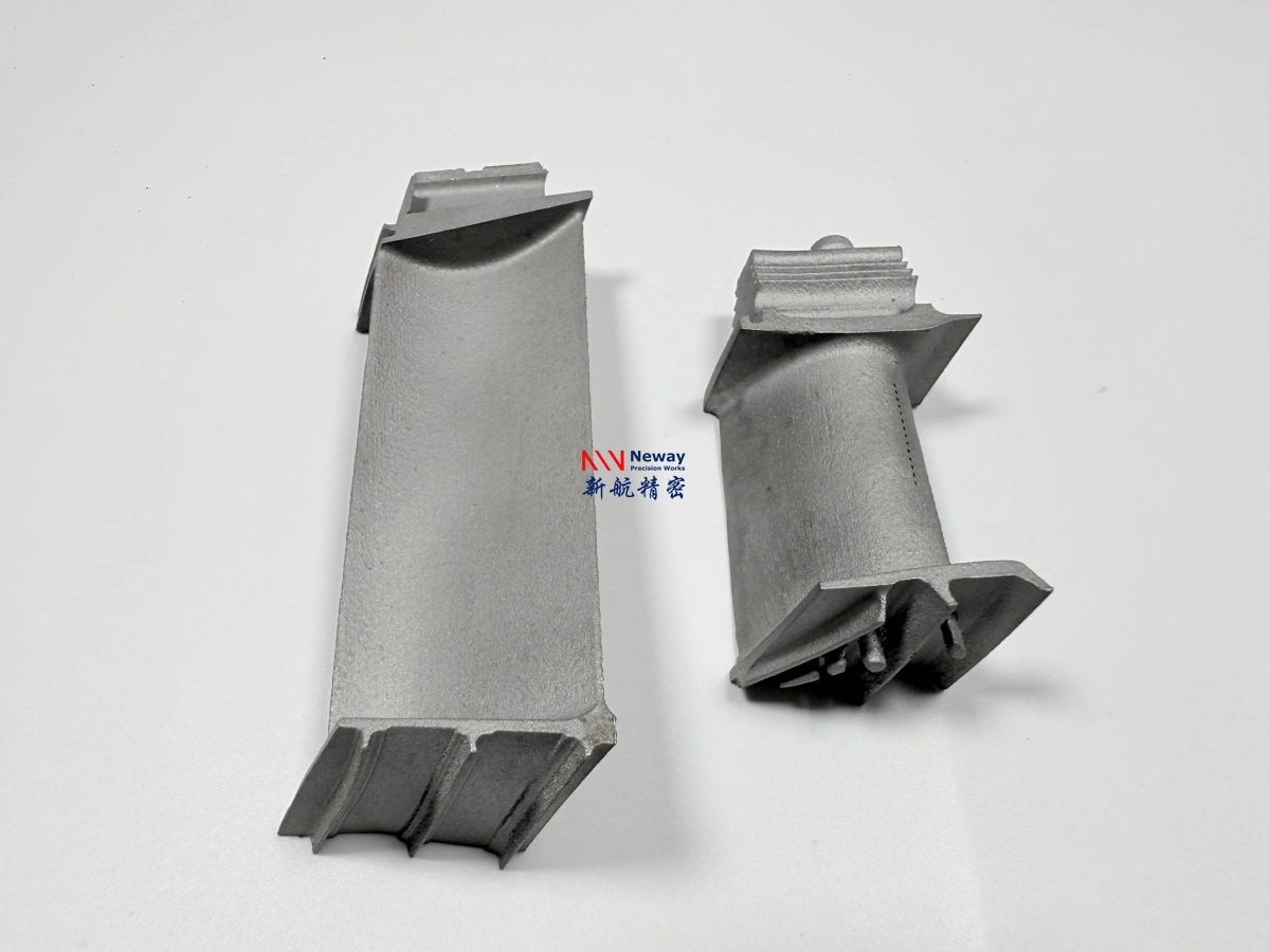
For GE 9E / 9171E turbine bucket manufacturing, the bucket body is usually produced from a high-temperature superalloy by casting or advanced solidification control. After the blank is produced, the root, platform, shroud, cooling holes, Z-notch areas, sealing faces, and coated surfaces must be processed carefully. NewayAeroTech supports Superalloy CNC Machining, Electrical Discharge Machining (EDM), Superalloy Deep Hole Drilling, Thermal Barrier Coating (TBC), and Superalloy Welding for custom hot section components.
1. Why Cooling Holes, Coatings, and Wear Areas Matter on GE 9E Turbine Buckets
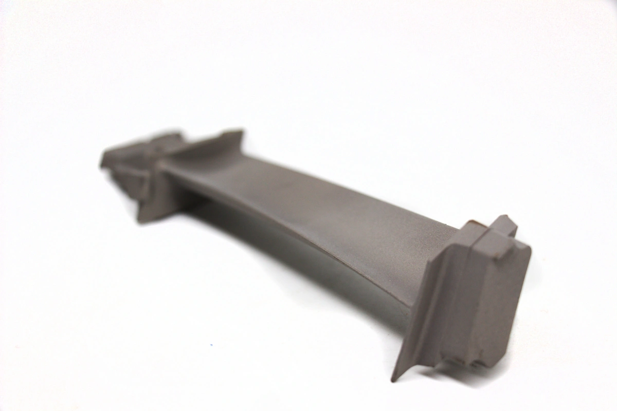
GE 9E turbine buckets work in high-temperature gas flow while also carrying rotating mechanical loads. The airfoil must resist heat, oxidation, creep, and fatigue. The root must fit securely into the rotor slot. The shroud and Z-notch areas must control contact, sealing, vibration, and wear. Cooling holes and coatings help reduce thermal damage and extend component life.
If cooling holes are inaccurate, blocked, oversized, undersized, or misaligned, cooling performance may be affected. If coating thickness or adhesion is unstable, the bucket may lose thermal protection. If Z-notch or shroud wear areas are not properly machined or hardfaced, contact damage and vibration-related issues may increase.
Feature | Why It Matters | Main Manufacturing Risk |
|---|---|---|
Cooling holes | Control metal temperature during hot gas path operation | Blocked holes, wrong angle, poor flow, burrs, recast layer |
TBC surface | Reduces thermal exposure on high-temperature gas path surfaces | Poor adhesion, uneven thickness, coating spallation, surface contamination |
MCrAlY bond coat | Improves oxidation resistance and supports TBC adhesion | Weak bonding, oxidation damage, coating mismatch |
Shroud surface | Controls tip area, sealing, contact, and vibration behavior | Profile error, wear, cracking, poor contact fit |
Z-notch hardface area | Improves wear resistance in contact zones | Cracking, poor weld bonding, excessive machining allowance loss |
2. How Are Cooling Holes Made in GE 9E Turbine Buckets?
Cooling holes in GE 9E turbine buckets are typically produced after the casting and heat treatment stages. Because turbine bucket materials are usually nickel-based superalloys or advanced high-temperature alloys, conventional drilling may not be suitable for all cooling features. EDM, laser drilling, or deep hole drilling may be selected depending on hole size, depth, angle, access direction, and airfoil geometry.
Electrical Discharge Machining (EDM) is suitable for small cooling holes, angled holes, narrow slots, and difficult profiles in hard superalloys. Superalloy Deep Hole Drilling can be used when long and relatively straight internal passages are required. For complex turbine bucket airfoils, inspection should confirm hole size, hole angle, cleanliness, and flow path consistency.
Cooling Feature | Possible Process | Quality Control Focus |
|---|---|---|
Film cooling holes | EDM drilling or laser drilling depending on geometry | Diameter, angle, exit quality, burr control, flow consistency |
Angled holes | EDM or controlled drilling with fixture support | Hole orientation, airfoil location, repeatability, surface condition |
Turbulated cooling features | EDM or specialized drilling process depending on design | Internal feature repeatability, blockage risk, cleaning accessibility |
Deep internal passages | Deep hole drilling or EDM according to access and depth-to-diameter ratio | Straightness, breakthrough risk, internal cleanliness, wall thickness control |
Narrow slots | Wire EDM or sinker EDM | Slot width, edge condition, recast layer, dimensional accuracy |
3. Why EDM Is Important for Superalloy Cooling Features
EDM is important because turbine bucket superalloys are difficult to machine by conventional cutting. Nickel-based alloys have high hot strength, low thermal conductivity, strong work-hardening tendency, and high tool wear. When cooling holes are small, angled, or located on curved airfoil surfaces, EDM can provide a more practical route than mechanical drilling.
However, EDM must still be controlled carefully. The process can create a recast layer or micro-cracks if parameters are not controlled. For critical turbine bucket features, EDM quality should be evaluated by dimensional checks, visual inspection, section analysis, flow testing, or CT inspection when required by the customer specification.
EDM Control Item | Why It Matters |
|---|---|
Discharge parameter control | Reduces excessive heat-affected layer and improves hole quality |
Electrode alignment | Controls cooling hole angle, position, and repeatability |
Flushing and cleaning | Prevents debris, blockage, and unstable discharge during machining |
Recast layer control | Improves surface integrity for fatigue and thermal cycling conditions |
Final hole inspection | Confirms that cooling features meet drawing and flow requirements |
4. How Are TBC and MCrAlY Coatings Applied to Turbine Buckets?
Thermal barrier coating is applied to turbine bucket surfaces that require thermal protection from hot gas exposure. A typical coating system may include surface preparation, MCrAlY bond coat, ceramic thermal barrier layer, and final inspection. The bond coat improves oxidation resistance and helps the ceramic layer adhere to the superalloy substrate.
Thermal Barrier Coating (TBC) must be planned together with machining allowance because coating thickness can affect final dimensions, clearance, surface roughness, and airflow. Coated areas should be defined clearly on the drawing, especially near root interfaces, platform surfaces, sealing areas, and cooling holes.
Coating Step | Purpose | Engineering Control |
|---|---|---|
Surface preparation | Removes contamination and prepares the substrate for coating | Cleanliness, roughness, masking, surface activation |
MCrAlY bond coat | Improves oxidation resistance and supports ceramic coating adhesion | Thickness, bonding, coverage, oxidation resistance |
Ceramic TBC layer | Reduces thermal exposure of the base superalloy | Thickness, uniformity, porosity, adhesion, thermal cycling behavior |
Masking and clearance control | Protects areas that must remain uncoated or dimensionally controlled | Root surfaces, mating faces, cooling hole exits, seal surfaces |
Final coating inspection | Verifies the coating meets drawing or specification requirements | Visual inspection, thickness inspection, adhesion review, surface condition |
5. How Are Shroud, Z-Notch, and Wear Areas Manufactured?
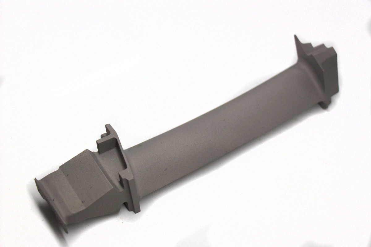
Shroud, Z-notch, and wear-contact areas on GE 9E turbine buckets require careful machining and surface treatment because these features affect tip sealing, vibration control, contact behavior, and long-term wear performance. These areas may require CNC machining, hardface welding, grinding, polishing, and surface inspection.
Wear-resistant materials such as Stellite 6 or Stellite 6B may be evaluated for hardface or contact regions. Superalloy Welding can be used for selected hardface zones, but the weld area must be inspected for cracks, bonding quality, and dimensional consistency after processing.
Wear Area | Manufacturing Method | Quality Control Focus |
|---|---|---|
Scalloped tip shroud | CNC machining, grinding, surface finishing | Profile accuracy, local thickness, contact surface, surface finish |
Z-notch area | Hardface welding, CNC finishing, FPI inspection | Crack control, weld bonding, wear resistance, dimensional recovery |
Sealing surface | CNC machining, coating control, surface finishing | Flatness, roughness, coating allowance, leakage control |
Contact interface | Wear-resistant alloy, hardface, machining, inspection | Contact pattern, surface integrity, long-term wear behavior |
Platform edge | CNC machining, blending, coating control | Edge condition, stress concentration, coating transition |
6. What Inspection Is Needed After Cooling Hole Machining and Coating?
After cooling hole machining and coating, inspection should confirm that the turbine bucket still meets dimensional, metallurgical, surface, and functional requirements. Cooling holes should be checked for size, angle, blockage, burrs, recast layer, and cleanliness. Coated surfaces should be checked for thickness, coverage, adhesion, surface condition, and masking accuracy.
NewayAeroTech provides Material Testing and Analysis for high-temperature alloy components. Depending on customer requirements, inspection can include CMM, 3D scanning, X-ray, CT, FPI, metallography, SEM/EDS, coating thickness inspection, and final visual review.
Inspection Item | Typical Method | Purpose |
|---|---|---|
Cooling hole diameter | Pin gauge, optical measurement, borescope, CT when required | Confirms hole size and repeatability |
Cooling hole angle | 3D inspection, fixture inspection, CT, or section analysis | Confirms hole direction and airfoil relationship |
Internal blockage | CT inspection, flow check, borescope, cleaning verification | Ensures cooling path is open and functional |
Recast layer | Metallographic section or SEM analysis when required | Evaluates EDM surface integrity |
Coating thickness | Thickness measurement and coating report | Confirms TBC, bond coat, or protective coating thickness |
Surface cracks | FPI or dye penetrant inspection | Finds open cracks after machining, welding, coating, or heat treatment |
7. What Information Should Buyers Provide for Cooling Hole and Coating Projects?
To manufacture GE 9E turbine buckets with cooling holes, coatings, and wear-resistant areas, buyers should provide detailed geometry, material, coating, and inspection requirements. Without cooling hole notes, coating thickness requirements, masking areas, and wear-zone specifications, the supplier may not be able to evaluate process risk accurately.
Required Information | Why It Matters |
|---|---|
3D CAD file | Supports airfoil geometry review, cooling hole orientation, and machining planning |
2D drawing with cooling hole notes | Defines hole diameter, angle, location, tolerance, and inspection requirement |
Material grade | Determines EDM difficulty, heat treatment, coating compatibility, and inspection method |
Coating specification | Clarifies TBC, MCrAlY, Al-Si, oxidation coating, thickness, and masking requirements |
Wear area requirement | Defines whether Stellite, hardface welding, grinding, or final machining is required |
Inspection standard | Confirms whether CMM, CT, FPI, metallography, coating report, or flow check is required |
Part stage and application | Helps evaluate temperature zone, stress condition, coating risk, and service requirement |
Quantity and delivery target | Helps evaluate fixture design, electrode preparation, coating batch, and lead time |
8. Practical Engineering Recommendation
For GE 9E turbine buckets, cooling holes, coating surfaces, and wear areas should be planned as one integrated manufacturing route. Cooling holes affect thermal performance, TBC and MCrAlY affect surface protection, and shroud or Z-notch hardface areas affect wear and contact behavior. These features should not be quoted or manufactured separately without reviewing the full bucket geometry and service requirement.
For faster technical evaluation, provide the turbine model, bucket stage, 3D CAD file, 2D drawing, material grade, cooling hole details, coating specification, wear-area notes, inspection standard, quantity, and target delivery schedule. NewayAeroTech can review the component and recommend a practical manufacturing route for GE 9E-type, 9171E-class, and other E-class turbine bucket applications.
GE 9E and 9171E names are used only to describe turbine-frame application requirements. NewayAeroTech focuses on custom manufacturing of superalloy parts according to customer-provided drawings, samples, specifications, and project requirements.