Exhaust Manifold Wax Injection Tooling: 4 Cavities, 2.2%
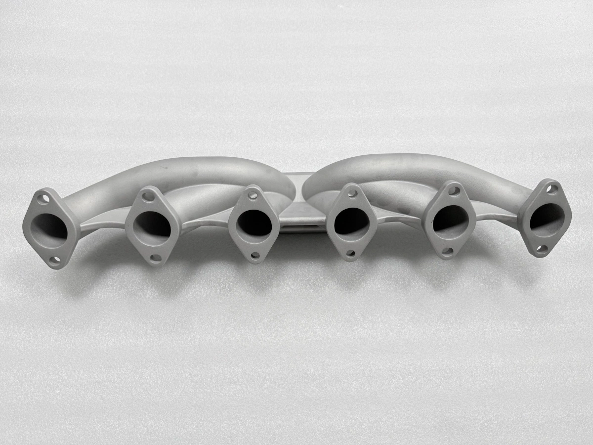
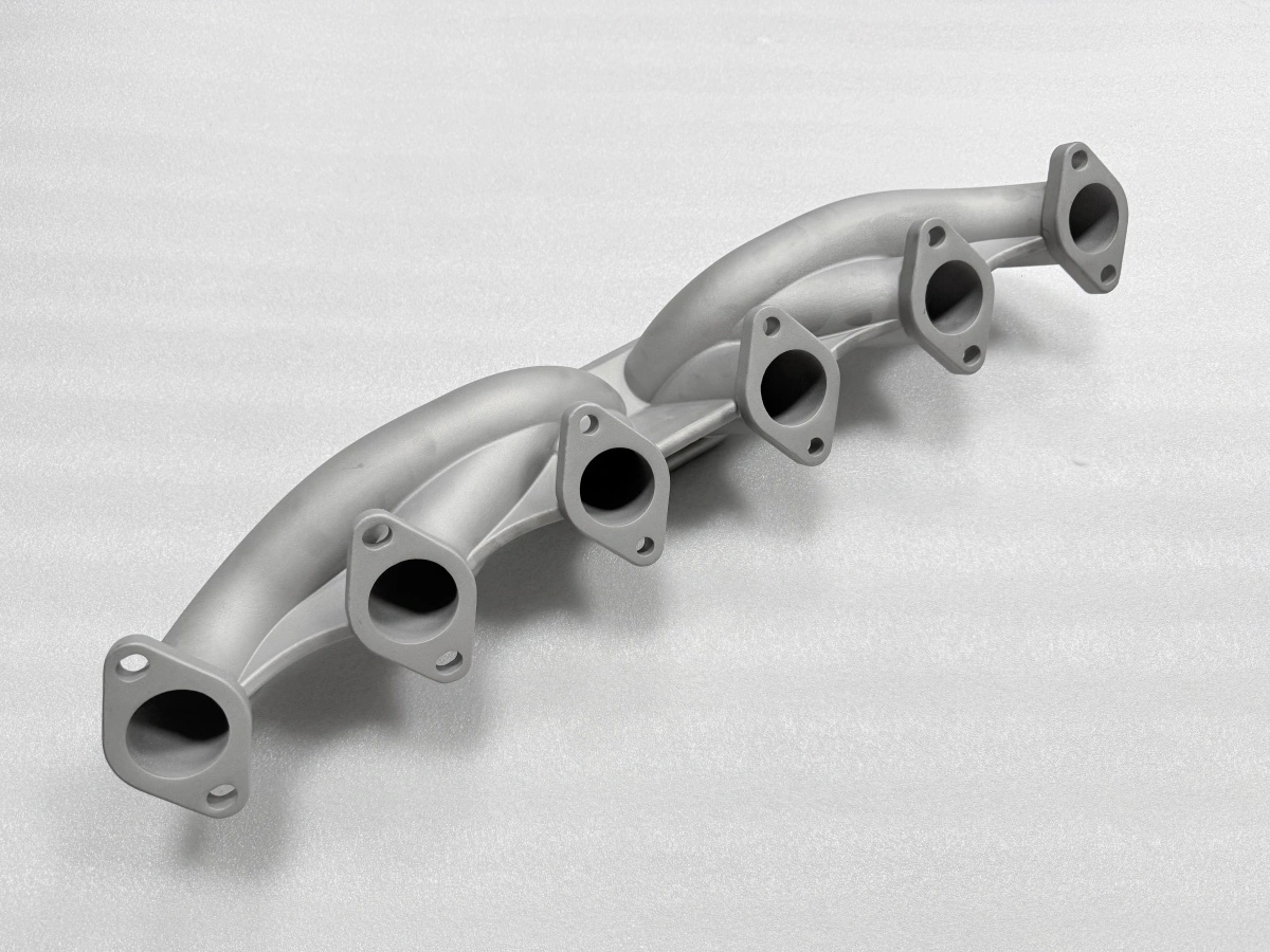
A 4-cavity wax injection tool turns a 2.5 mm stainless exhaust manifold into a repeatable casting, provided the cavity is cut at 2.2% compensation and the six faces keep 1.5 mm for machining. The route has three gates: the tool must close to 0.05 mm, the shell must survive seven layers, and the pour must fill walls that thin under vacuum. Miss any one gate and the part is a pattern, not a product.
Why tool an exhaust manifold instead of printing a pattern?
A printed pattern makes sense for one part or for a geometry that is still moving. A manifold at production volume is the opposite case: the design is frozen, the features repeat, and the cost of the part depends on how many times the cavity can be reused. Tooling buys that repetition.
The trade is upfront weeks for downstream consistency. A four-cavity tool produces eight patterns per tree and lets every pattern be measured against the same cavity rather than against a print file that changes with each build. On this manifold, the cavity also carries the 2.2% shrinkage compensation, so the wax pattern is measured against a CAD model that already includes the allowance the casting will need. That single decision removes the most common argument in a first-article review: whether a dimension that reads 0.1 mm over is a cavity error or a compensation error.
Printing a pattern is still the right answer before the design is frozen, or below roughly 300 parts where the tool cost never amortises. Above that, the wax tool is what makes the precision wax pattern creation repeatable instead of artisan. Printing also carries a cost that is easy to miss: each pattern is a new build, so a batch of 300 patterns is 300 chances for the print file to drift. A cavity does not drift on its own; it wears, and wear is measurable.
Cutting the cavity: parting, ejectors and 2.2% compensation
The cavity is cut to the compensated model, not to the drawing. Compensation is applied as a uniform 2.2% scale before the tool paths are generated, and the parting lines and ejector positions are then placed on the compensated geometry, not on the nominal one. Reversing that order is a common way to lose 0.2 mm on the flange centers. The scale is applied once, on the CAD model the tool paths are cut from, and every downstream measurement is taken against that same model.
This manifold uses three parting faces and eight ejector points. The three faces matter because the runners sit at different heights; a single flat parting would trap the pattern at the sixth runner. The eight ejectors are placed on the boss faces rather than on the sealing faces, because an ejector mark on a sealing face becomes a leak path after machining.
The tool closes on a 0.05 mm gap, checked with a feeler at each corner before the first shot. An automatic wax press holds the clamp force during the shot, but it cannot correct a parting face that was fitted badly.
Tool parameter | Value | Why it is set here |
|---|---|---|
Cavities | 4 | Eight patterns per tree with two trees per shift |
Shrinkage compensation | 2.2% | Uniform scale applied before tool paths |
Parting faces | 3 | Runner heights differ along the body |
Ejector points | 8 | On boss faces, away from sealing faces |
Parting gap | 0.05 mm | Feeler check at each corner |
Wax temperature | 75 °C | Fills 2.5 mm walls without short shots |
Injection pressure | 0.3 MPa | Lower pressure keeps flash under 0.1 mm |
Hold and cooling | 8 s / 60 s | Pattern releases without distortion |
The table is the tool card in short form: every number on it is a setting that gets checked on the first pattern, not a nominal that gets assumed. A setting that is not on the card is a setting that gets improvised at the press, and improvisation is what makes two shifts produce two different patterns.
How wax becomes a shell on a 2.5 mm manifold
Eight patterns are assembled on one runner tree, gated so that each pattern sees the same slurry flow. The tree then takes seven ceramic layers, each about 8 mm of build and 8 h of drying, which puts the shell at roughly two and a half days of calendar time before dewaxing. The layer count is not arbitrary: fewer layers leave the shell too weak at the runner junctions, where the slurry pools and dries unevenly. Each layer is checked for thickness and for any bridging between the runners before the next dip, because a bridge found after the seventh layer means the tree is scrap.
Dewaxing runs at 165 °C and 7 bar. The pressure matters as much as the temperature, because a 2.5 mm wall pattern expands faster than a thick one and will crack a shell that was dried too quickly. The burnout follows at 1000 °C for 1.5 h, which is long enough to clear the last carbon from the runner bores and short enough to keep the shell from slumping.
Shell building is where thin-wall manifolds are usually lost. An automated shell building line keeps the dip and dry cycle repeatable, but the layer count still has to be set from the geometry rather than from the standard recipe. On this part the count was fixed at seven after the first tree showed a soft spot at the junction between the second and third runner.
Pouring the thin walls at 1600 °C under vacuum
The pour runs at 1600 °C with the mold under −0.05 MPa and a 12 s fill. The vacuum does two jobs: it pulls gas out of the shell so the metal does not fold it back into the wall, and it holds the thin sections open long enough for the metal to reach the sixth runner before the leading edge freezes.
Twelve seconds is the number that gets argued about most. A slower fill gives a cleaner surface but risks a cold shut at the far runner; a faster fill fills the wall and carries more turbulence into the bore. On this manifold the fill is set from the thinnest section, then verified on the first casting rather than optimized on the drawing. The first casting is cut at the runner and checked for a cold shut before the fill time is locked into the process card. The practice behind that choice is set out in precision pouring.
After the pour the part is stress relieved at 880 °C for 3 h before any machining. Skipping that step does not show up on the first part; it shows up as a flange that moves 0.1 mm after the third week of machining, which is the failure mode described in stress relief in castings. The relief is not optional on a manifold with six thin flanges; it is the step that lets a 0.05 mm flatness survive the machining sequence.
Machining six manifold interfaces in three setups
The casting arrives with 1.5 mm of stock on the six runner faces and on the head flange. Three setups cover the part: the head flange and two runner faces in the first, the remaining four runner faces in the second, and the bolt holes in the third. The order is set by the datum, not by convenience; machining the four faces before the head flange would move the datum twice. Each setup is probed against the same datum feature, so a shift in setup two shows up as a flatness error in setup three rather than as a silent stack-up.
Flatness is held at 0.05 mm on each sealing face, and the faces are checked on a surface plate before the holes are drilled. The general tolerance on the casting itself is CT6 under ISO 8062-3, which leaves 0.9 mm of form deviation that the 1.5 mm stock has to absorb along with the machining allowance.
Machining step | Faces covered | Stock removed | Check |
|---|---|---|---|
Setup 1 | Head flange + 2 runner faces | 1.5 mm | Flatness 0.05 mm |
Setup 2 | 4 runner faces | 1.5 mm | Flatness 0.05 mm |
Setup 3 | Bolt holes | Drill only | Go/no-go gauge |
Both tables carry the same numbers that appear in the text, so a reader can check a claim against a row instead of against a paragraph. The CNC machining service runs the three setups on one datum chain, and the reasoning behind the stock figure is set out in CNC machining on castings. Hole positions are checked with a go/no-go gauge on the third setup; a hole that passes the gauge but sits 0.2 mm off the datum shows up later as a flange that will not seat.
When exhaust manifold tooling is the wrong route
Tooling is wrong below roughly 300 parts, and it is wrong before the design is frozen. A cavity cut against a drawing that is still moving will be re-cut at least once, and a re-cut parting face costs a week plus a re-fit. It is also wrong when the wall drops below 2 mm: the wax pattern still fills, but the shell cannot hold the thin section through dewaxing often enough to make the yield work.
The route also stops at the certification boundary. A CT6 casting with a dimensional report supports a production decision; it does not support a fatigue life claim, a pressure test result, or a customer acceptance signature. Those come from the customer's own validation, not from the foundry's inspection sheet. What the foundry can hand over is a dimensional report and a material certificate, and both are worth having before a customer validation starts.
For quantities under 300 or geometries still in review, a printed pattern or a machined prototype is the cheaper answer, and the casting route is what you move to once the design stops changing. A production case on stainless steel casting production shows where that switch happened on a comparable part. Dimensional control on the finished casting is covered in dimensional control, and the heat treatment behind the 880 °C relief runs on the heat treatment service line.
Send the drawing and the annual volume; we will return a tooling decision with the cavity count, the compensation figure and the machining stock that fits your part, priced with the vacuum investment casting route before the cavity is cut. If the volume does not carry a tool, we will say so in the same reply.
FAQs