Stress Relief in Castings: Key to Dimensional Stability
A stress-relief cycle does not make a casting dimensionally stable by declaration. It releases part of the residual-stress field created by solidification, cutoff, straightening, weld repair, blasting, and machining. The geometry that appears after release can be different from the geometry measured before the cycle. Buyers therefore need a route that measures movement and preserves machining stock, not a generic heat-treatment note.
For this RFQ, define the exact alloy and casting structure, incoming thermal condition, free-state datums, critical geometry, manufacturing sequence, expected stock removal, fixture concept, approved temperature window, and pre/post-cycle inspection. The supplier cannot choose a defensible stress-relief heat treatment until those boundaries are clear.
Map Where Residual Stress Enters the Casting Route
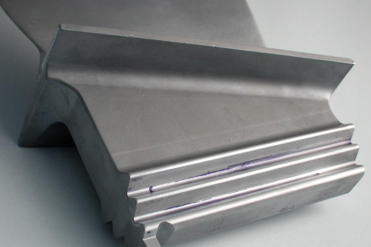
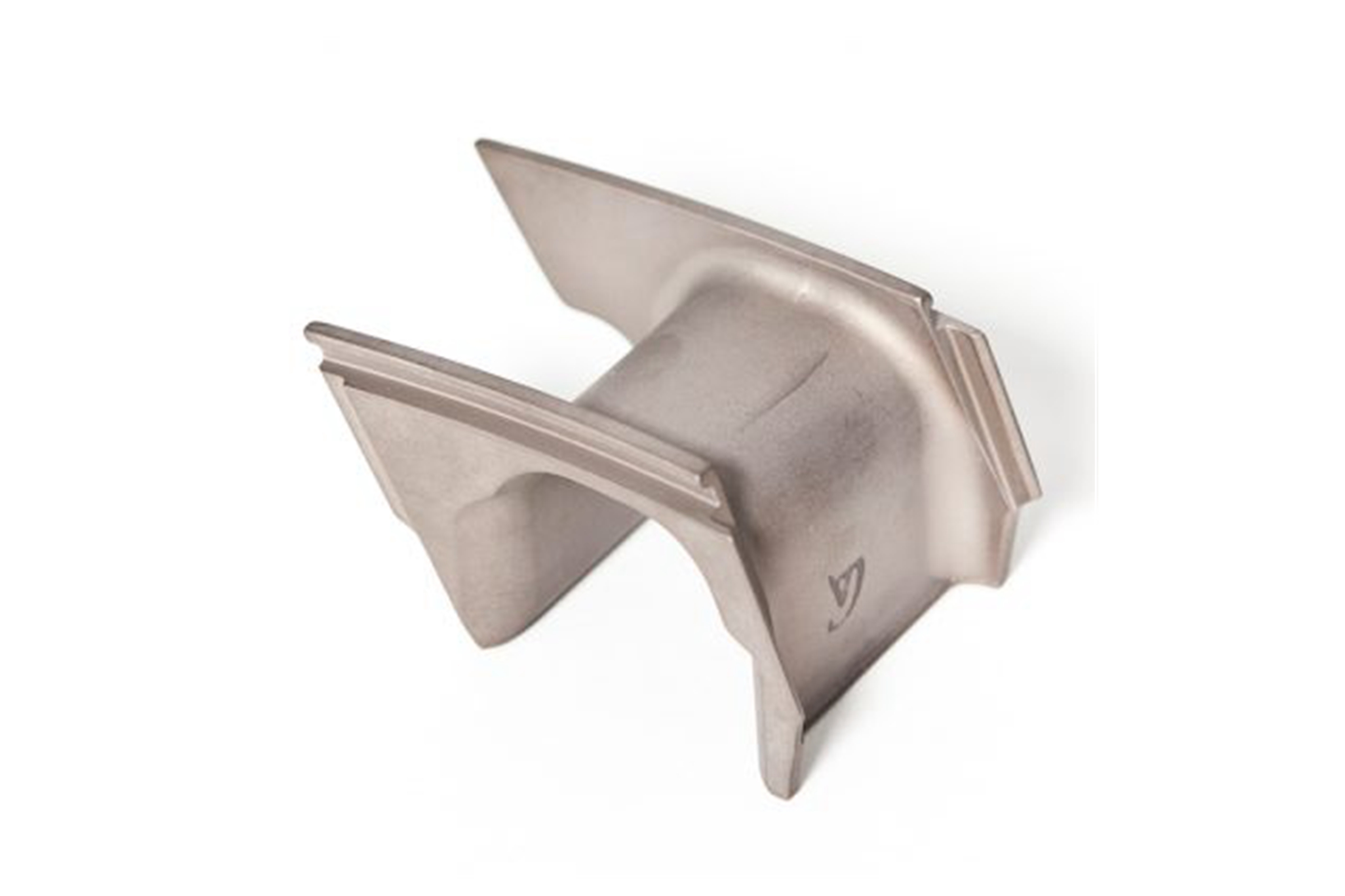
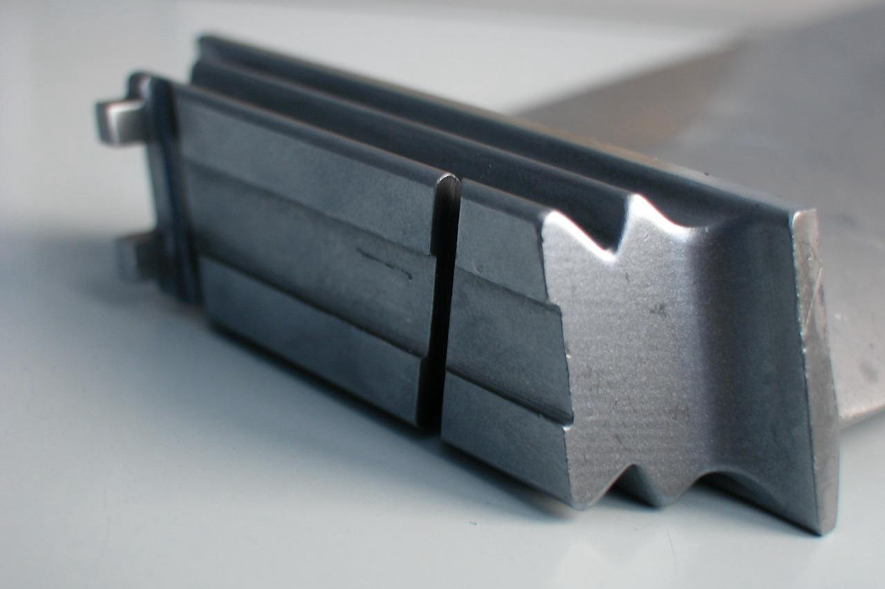
Residual stress begins with uneven solidification and cooling. Heavy-to-thin transitions, constrained cores, long spans, rings, flanges, blade platforms, bosses, and abrupt section changes can cool at different rates. Gate and feeder removal, shell knockout, core leaching, abrasive cleaning, local straightening, and weld repair then modify the stress field before machining starts.
Machining removes load-bearing material asymmetrically. A large cavity opened from one side, a deep bore, a thin flange face, or heavy stock removal near one datum can release stress and change bow, twist, runout, flatness, or concentricity. The route should identify high-removal operations and the geometry to be checked immediately afterward.
Build a process map that records each thermal and mechanical input. Alloy heat, casting lot, cutoff method, repair, roughing setup, stock removed by side, fixture force, intermediate dimensions, and furnace cycle should remain traceable to the finished part. This lets the team distinguish foundry variation from machining- or heat-treatment-driven movement.
Define the Free-State Measurement Condition
A flexible casting can appear acceptable while clamped and move after release. The drawing or inspection plan should state whether dimensions are checked free, supported at designated points, or restrained in a functional fixture. Support location, orientation, settling time, and measurement temperature must be repeatable across pre-cycle, post-cycle, and final inspection.
Use functional datums rather than whichever surface is easiest to place on a table. For a ring, define axis and roundness references; for a housing, identify mounting pads and bore relationships; for a blade or vane, establish root or platform datums and profile sections; for a long casing, define support spacing and straightness reference.
Measurement uncertainty and method must suit the expected movement. CMM, scanning, runout fixtures, optical methods, contour templates, bore gauges, and surface plates answer different questions. Record the same characteristics with compatible methods before and after stress relief so the delta is real rather than a change in setup.
Place Stress Relief at the Correct Machining Stage
Route point | Purpose | Key risk to control |
As-cast before major cutting | Reduce part of the foundry and cutoff stress before roughing | Scale, support, and later machining still alter geometry |
After balanced rough machining | Release stress exposed by substantial stock removal | Enough stock must remain for correction |
After weld repair | Address approved repair thermal stress where the alloy route requires it | Repair acceptance and microstructure remain separate |
Between deep-hole or cavity operations | Stabilize geometry before critical relationships are finished | Re-datum after the cycle and protect passage geometry |
After finish machining | Usually limited by final-size and surface risk | Movement may leave no stock for recovery |
A common route is to rough both sides or opposing features in a balanced sequence, leave feature-specific stock, stress relieve, re-establish datums, and then finish. This is not universal. Thin near-net castings, precipitation-strengthened alloys, single-crystal parts, and components with prior approved heat treatment may have tighter thermal restrictions.
Coordinate stress relief with CNC machining and deep-hole drilling. The machining supplier should state setup sequence, stock-removal balance, clamping strategy, datum-transfer plan, and inspection points. Otherwise a sound furnace cycle can be followed by another uncontrolled stress release.
Protect Alloy Microstructure While Releasing Stress
Stress-relief temperature and time must remain compatible with the alloy's solution, aging, carbide, and precipitate condition. A cycle chosen only from part size can overage a precipitation-strengthened alloy, interact with prior thermal exposure, or approach a sensitive temperature range. Exact grade, specification, delivery condition, section thickness, and complete thermal history are required inputs.
Equiaxed, directionally solidified, and single-crystal castings need structure-specific review. Grain-boundary response, anisotropy, recrystallization risk, incipient melting, coating or diffusion history, and surface chemistry can restrict the cycle. A general schedule for “nickel alloy” is not an adequate instruction.
Specify furnace atmosphere or vacuum, cleanliness, ramp, soak definition, sensor method, cooling, load arrangement, and deviation rules as required by the governing specification. The furnace record should identify actual lot and cycle. Stress relief should be distinguished from solution treatment, aging, homogenization, and HIP even when temperature ranges overlap.
Design Supports That Permit Controlled Movement
At temperature, a casting can move under self-weight while residual stress relaxes. Long spans may bow, rings may ovalize, flanges may dish, and thin airfoils may sag or contact adjacent parts. Load diagrams should define orientation, support points, spacing, nesting, clearance, and the surfaces allowed to contact fixtures.
A fixture should support the part without forcing it to a target shape. Heavy restraint can mask free movement during heating and introduce stress through differential thermal expansion. If tooling is required, document material, contact geometry, thermal compatibility, inspection, and whether the part is measured restrained or after fixture removal.
Fixture design should preserve gas circulation and avoid contamination or local thermal shielding. Mark lifting and handling points so operators do not load thin walls or finished interfaces while the part is hot. Cooling and fixture-removal instructions belong in the route, not in undocumented shop practice.
Allocate Machining Stock by Feature Risk
One uniform stock allowance rarely protects every dimension. A seal face may need stock for flatness recovery, a long bore for axis correction, a bolt pattern for datum transfer, and an airfoil or passage wall for minimum-thickness protection. Create an allowance map tied to the expected direction and magnitude of movement from first-article data.
Stock must be evaluated as a geometric envelope. Enough radial material does not help if a bore centerline shifts beyond the outer wall, and extra face stock does not recover a bolt pattern that moves relative to its datum. Use worst-case relationships among datums, minimum walls, and finish surfaces.
After stress relief, inspect before committing to expensive finishing. Re-baseline critical datums, confirm stock distribution, and route outliers through an approved disposition. Repeated straightening or another thermal cycle should not be used without checking alloy limits and the effect on the validated route.
Separate Stress Relief from Defect Repair
Stress relief does not close casting porosity, remove inclusions, heal cracks, replace missing wall, clean blocked passages, or restore oxidized material. It may reduce some residual-stress contribution to distortion or cracking, but defect type and root cause remain. Keep NDE acceptance and thermal-process acceptance as separate decisions.
If weld repair is permitted, define defect excavation, maximum repair size and location, filler, heat input, preheat, interpass control, post-weld cycle, blend, and inspection. The repair can create a localized stress and microstructure field that needs its own evidence. A generic stress-relief callout does not authorize welding.
Where HIP is also used, establish the order and purpose of each cycle. HIP targets eligible sealed internal porosity under pressure and temperature; stress relief targets a residual-stress condition; solution and aging target microstructure. The quote should not collapse them into one unnamed “post-process.”
Prove Dimensional Stability with First-Article Deltas
The first article should record dimensions at controlled checkpoints: as-cast or incoming, after roughing, after stress relief, after any follow-up thermal operation, after datum re-establishment, and after finish machining. Plot the change by characteristic and direction. A final pass alone cannot show where movement occurred or whether stock margins are repeatable.
Use the results to revise casting offset, rough-machining balance, support arrangement, cycle placement, and allowance map. If repeated parts move consistently, compensation may be possible under design and process control. If movement varies widely, investigate casting, repair, fixture, furnace loading, or machining inputs before tightening final inspection.
Confirm material condition as well as geometry. Where required, use material testing and analysis for hardness, microstructure, or other specified checks. Dimensional stability is not acceptable if the route leaves the alloy outside its required metallurgical condition.
Control Repeat Lots and Process Changes
Freeze alloy source and condition, casting route, cutoff, repair, rough-machining sequence, stock map, stress-relief cycle, furnace source, load orientation, fixtures, cooling, metrology setup, and finish route at the level required by approval. Define changes that trigger notification or repeat first-article review.
Trend movement by feature and lot. A gradual change in flange flatness, ring ovality, bore shift, or profile may reveal drift in casting layout, fixture wear, furnace loading, or roughing balance. Review the trend before final dimensions consume all available stock.
The release package should link heat-treatment chart, load identity, pre/post dimensional results, NDE, deviations, and final inspection to the shipped component. A furnace certificate without part-specific geometry evidence cannot demonstrate dimensional control.
Build a Stress-Relief RFQ That Can Be Quoted
Send the controlled drawing and model, exact alloy and casting structure, component condition, prior thermal history, critical datums and geometry, free or restrained inspection state, anticipated movement, roughing and finishing sequence, stock map, repair history, proposed cycle or governing specification, furnace requirements, support concept, inspection methods, first-article plan, records, and change-control expectations.
Request separate pricing for baseline measurement, fixture design, rough machining, stress relief, repeat metrology, material checks, straightening review, finish machining, NDE, and documentation. State which party owns technical disposition if movement exceeds the available envelope.
A usable proposal should explain when the cycle occurs, which residual-stress sources it addresses, what geometry may move, how the alloy condition is protected, and how success will be measured. That turns dimensional stability from a broad promise into a controlled sequence with evidence.
Related FAQs
Why Is Stress Relief Crucial for Superalloy Castings in High-Performance Applications?
What Are the Primary Techniques Used in Stress Relief for Superalloys?
Stress Relief in Superalloy Castings: Impact on Dimensional Stability and Fatigue Life
Challenges in Stress Relieving Superalloys: Temperature Control, Distortion, and Microstructure
How Does Stress Relief Contribute to the Extended Lifespan of Superalloy Components?
How Long Does a Typical Stress Relief Heat Treatment Cycle Typically Take?