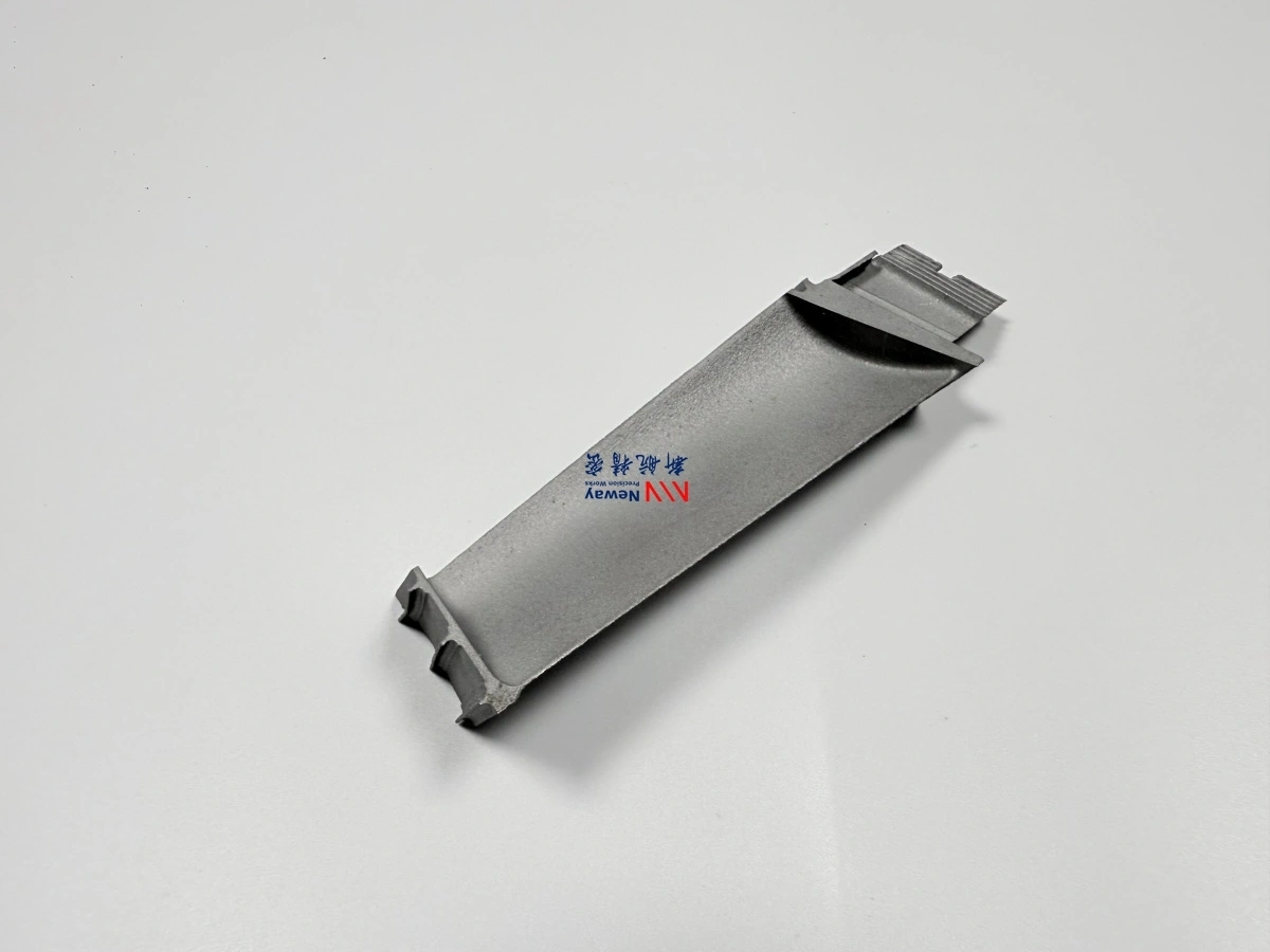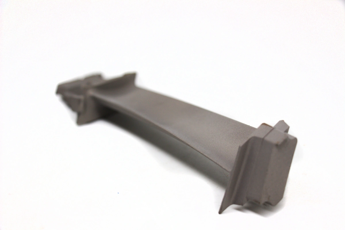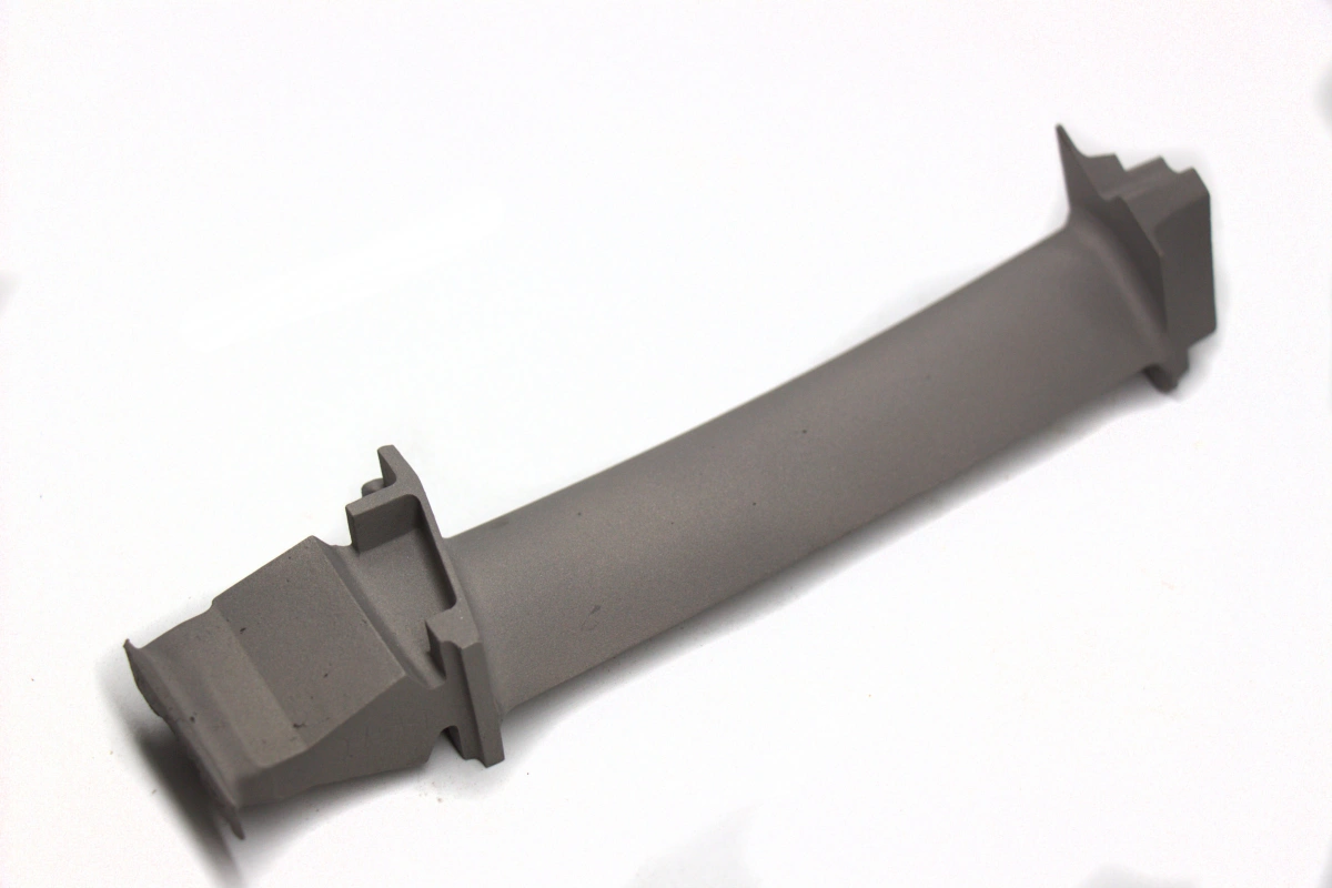
How Much Machining Allowance Do Exhaust Manifold Flanges Need?
An exhaust manifold flange machining allowance of 1.5 mm lets three setups hold 0.05 mm flatness on all six runner faces and the turbo flange. A 1.0 mm allowance left two runner faces partly un-machined on this manifold. The extra 0.5 mm costs one roughing pass and removes a rework risk.
How much exhaust manifold flange machining allowance is needed?
1.5 mm is the working allowance for the six runner faces and for the turbo flange. A cast face is never flat enough to seal on its own: CT6 under ISO 8062-3 allows 0.9 mm of form deviation across a flange, and that deviation has to come out of the stock. With 1.0 mm of stock, the low point of a deviated casting reaches the finished surface before the high point is cut.
That exhaust manifold flange machining allowance also has to cover the casting skin. Shot blasting leaves a 0.1–0.2 mm layer at Ra 3.2–6.4 µm, and the finishing cut has to go under that layer, not blend into it. With vacuum investment casting, a 1.5 mm allowance puts the finished surface 0.3–0.5 mm below the blasted skin on the thinnest ear.
Why did 1.0 mm leave black skin on six flanges?
On the first run of this manifold, the exhaust manifold flange machining allowance was cut at 1.0 mm on all six faces. Two of the six came out with black skin at one ear: the casting sat low there and the finishing pass ran out of stock before the face cleaned up. The measured shortfall was under 0.2 mm, which is exactly the margin that a 1.0 mm allowance does not have.
The fix was not more finishing passes. The six mounting faces were given 1.5 mm and the thinnest ear got an extra 0.5 mm, so the finishing pass had stock to cut regardless of where the casting sat. The second run cleaned all six faces, and the allowance has stayed at 1.5 mm since.
How are six manifold faces machined flat in three setups?
Three setups, one datum chain, and a stress relief between roughing and finishing carry the faces from cast to 0.05 mm flat. Each setup has a number that matters.
Setup 1: face-mill the turbo flange and ream two datum holes, with clamping force at 1.0 MPa or less; this face and these two holes locate everything that follows.
Setup 2: rough the six runner faces at 0.4 mm radial and 2.0 mm axial depth on the same datum, leaving 0.5 mm of stock; then unclamp the part and re-check after stress relief.
Setup 3: semi-finish to 0.15 mm of stock at 0.25 mm radial depth, then finish at 0.1 mm radial and 0.4 mm axial depth, before drilling and tapping the M10×1.5 threads.
What flatness is held and how is it checked?
Flatness is held to 0.05 mm on the six runner faces and on the turbo flange. Mid-process flatness after roughing is allowed to sit at 0.08 mm, because the finishing pass removes 0.15 mm and re-seats the face; that difference is a process window, not a second specification. Measurement is a surface plate and a CMM, and the finish cut is planned around the dimensional control in investment casting limits of the casting rather than around the machine.
Two checks catch the failure modes early. A CMM check after roughing finds a face that twisted under clamping, and a flatness check on the free part after unclamping separates spring-back from a real machining error. The finishing cut uses superalloy CNC machining practice for clamping and cutter engagement, which matters more on a thin flange ear than the spindle speed.
When is allowance the wrong fix?
Adding stock does not fix a casting that moves after machining. If the flange ears are thinner than 2 mm, extra stock makes the ear stiffer to cut but no flatter: clamping distortion dominates, and the face springs back after unclamping. If flatness fails because residual stress is released during the cut, the answer is stress relief at 880 °C for 3 h before finishing, not more allowance.
Allowance above 2 mm only buys cycle time. Beyond that point the casting tolerance, not the stock, sets the flatness; the CNC machining on castings route then needs a different datum or a different casting, and a supplier that keeps adding stock will keep missing the number.
Send the drawing with the flange callouts and the datum scheme, and we will return an allowance and setup plan for the six faces, with the flatness check points marked, before any quote is issued.