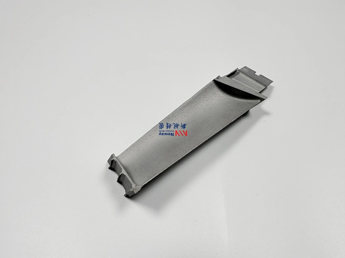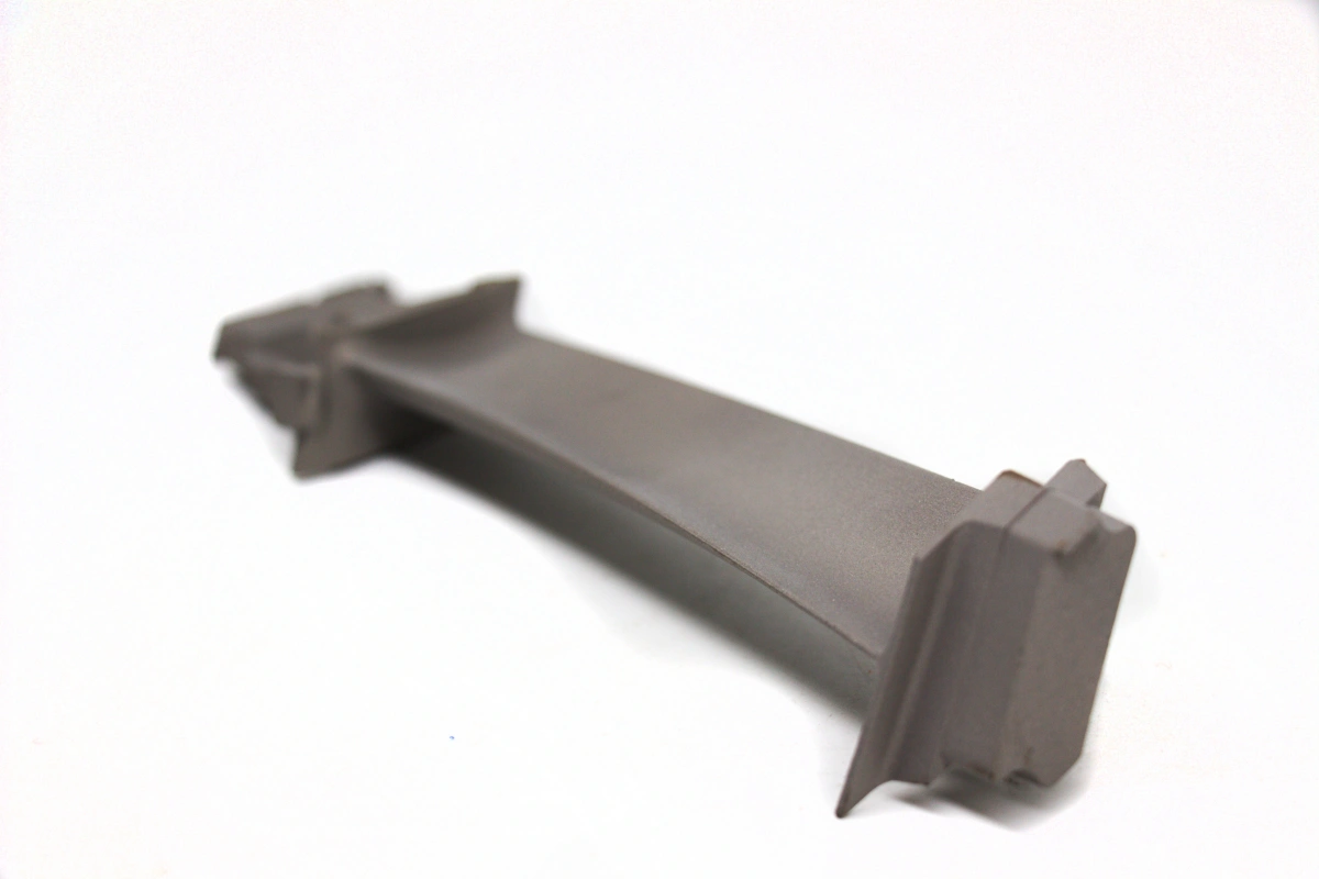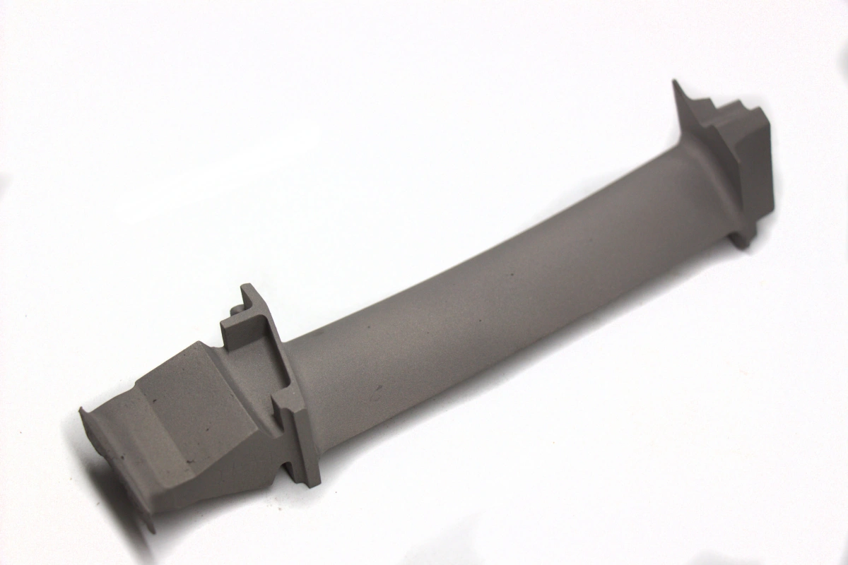
Exhaust Manifold Wax Pattern: What Does a First Article Prove?
The first exhaust manifold wax pattern proves the cavity size, the parting-line flash and the 2.2% shrinkage compensation before production wax is injected. It is a tool check, not a casting release. A pattern that passes still has to survive shell build, pour and the first cast inspection.
What is measured on the first exhaust manifold wax pattern?
Four measurements decide whether the tool is ready to run. The first is the body length from datum to datum, compared with CAD after the 2.2% compensation is applied. The second is the six runner flange positions, checked as a pattern of centres rather than one flange at a time.
The third is wall thickness at three points on the thinnest runner, taken with a small ball gauge. The fourth is flash along the parting line, measured where the two halves close last.
\n
The order matters. Body length and flange pattern come first, because a cavity correction fixes them; wall thickness second; flash last, because it answers whether the tool closes, not whether it is the right size.
Why does flash matter more than size on day one?
A size error of 0.1 mm on the first pattern is a linear correction to the cavity, and it repeats predictably on every part. Flash is not linear. It says the two halves do not close at that corner, and the gap will move as the tool heats and the press cycles. On the first pattern of this manifold, flash measured 0.2 mm at one parting corner while the body dimensions sat inside 0.1 mm.
Grinding the parting faces to a 0.05 mm gap and dropping the injection pressure from 0.35 MPa to 0.3 MPa removed the flash on the next pattern. The size stayed where it was. That is the pattern: flash is a tool-closure problem with a mechanical fix, and size is a cavity problem with a dimensional fix.
Flash also hides in the part. A 0.2 mm fin across a runner becomes a folded edge in the shell, and the casting shows it as a linear inclusion.
How does the first article set production parameters?
The first article fixes the four numbers the press runs on: wax at 75 °C, injection pressure at 0.3 MPa, hold for 8 s, and cooling for 60 s before the pattern leaves the tool. These come from the settings the first article responded to, recorded on the tool card.
The parameters also define the correction window. If the first pattern comes out 0.1 mm beyond the compensation, the cavity is adjusted by that amount and the next three patterns confirm it. If it is out by more than 0.2 mm, the tool is corrected before any more wax is injected, because the same small error repeated across 4 cavities turns into a batch problem.
\n
The same exhaust manifold wax pattern is later checked against CT6 under ISO 8062-3, so the wax band has to leave room for that tolerance. The precision wax pattern creation stage ends only when the correction is confirmed by a second pattern, not by the first one.
When is the tool sent back for correction?
The tool goes back when the error lives in the cavity, not in the press. Parting-line flash, a cavity dimension outside 0.1 mm after compensation, and a core that shifts between cavities are all tool corrections. Pressure, temperature and cooling are press settings, and using them to hide a cavity error usually moves the defect instead of removing it.
On the first run of this manifold the parting faces went back for grinding while the press settings stayed. The tool returned with a 0.05 mm gap, flashed 0.1 mm or less, and production started. The 2.2% compensation was left untouched because the body dimensions were already inside the band.
\n
An automatic wax press makes this loop shorter, because the same pressure and hold repeat without operator drift, but it does not replace the correction decision.
What does the first article not prove?
The wax pattern is not the casting. It proves the tool, not the alloy: shrinkage through shell build, pour and cooling is measured on the first cast part, not on wax. Fatigue life, pressure tightness and customer acceptance sit outside a first-article wax check.
A pass also does not prove the process window. It proves one pattern on one day; the batch is proven when three patterns repeat inside the band and the first casting passes its own check.
Send the drawing and the CAD model with the shrinkage already applied, and we will return a first-article plan with the four wax measurements, the flash limit and the correction window, priced with the vacuum investment casting route, before the tool is cut.