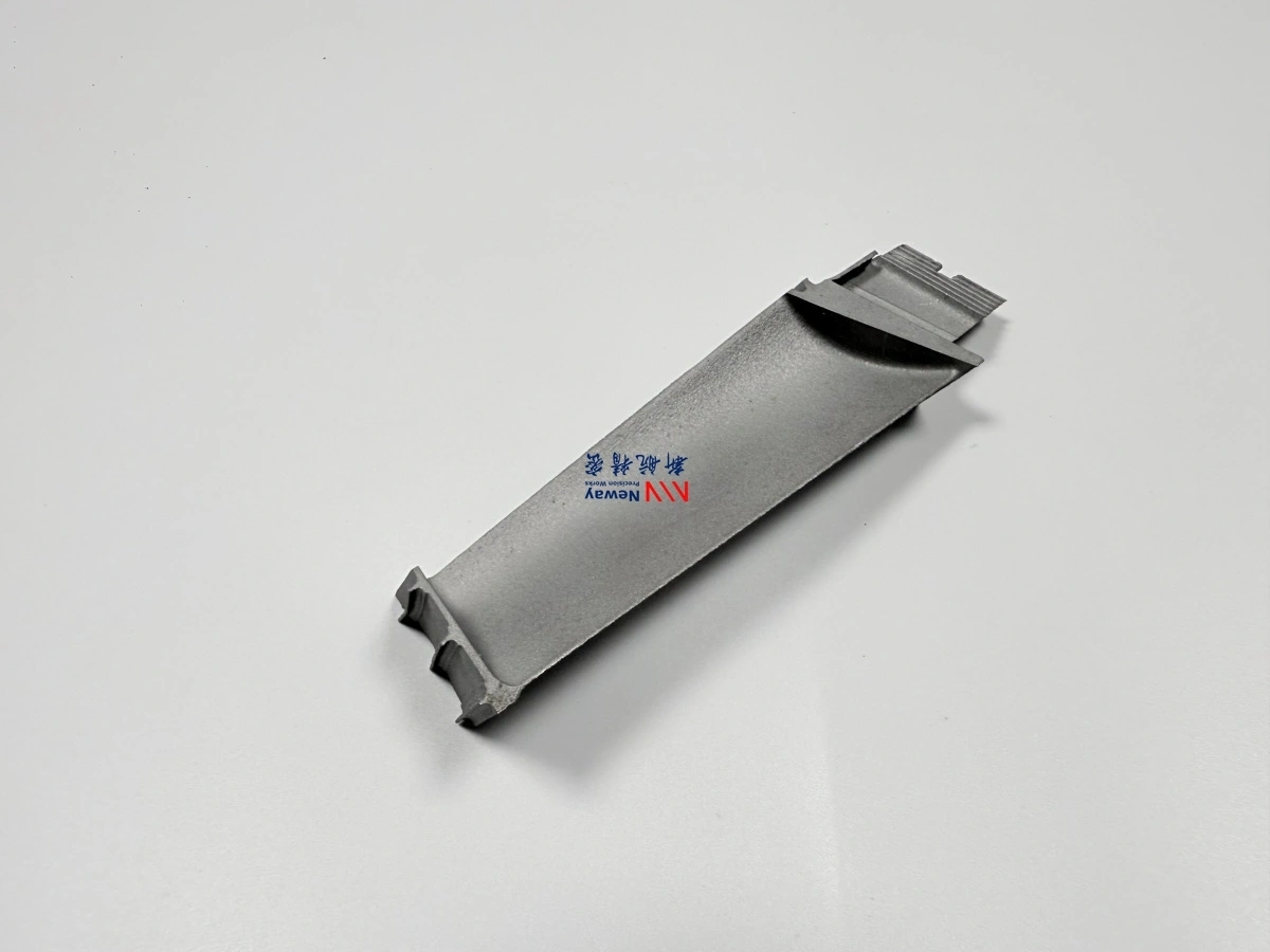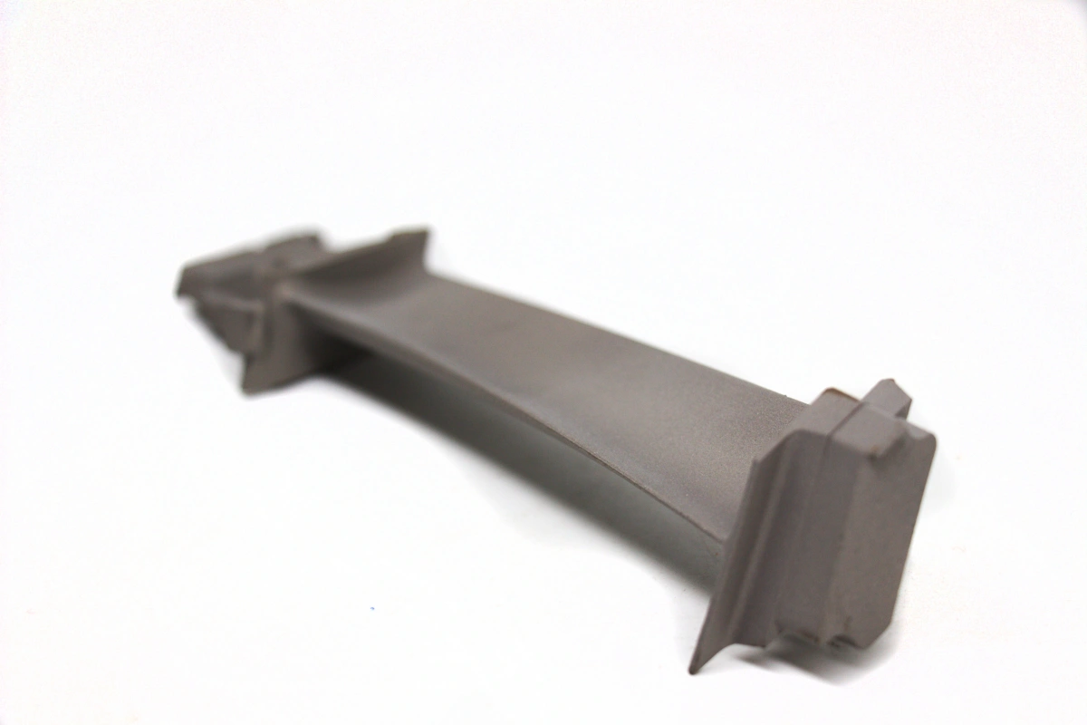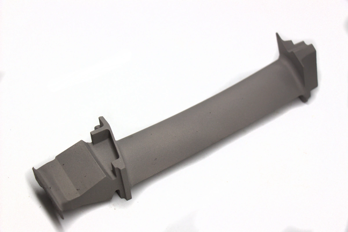
Exhaust Manifold Wall Thickness: Can 2.5 mm Cast Reliably?
An exhaust manifold wall thickness of 2.5 mm fills reliably at 1600 °C in a 7-layer shell built for vacuum investment casting. Below 1.5 mm the same geometry becomes a research problem rather than a production route. The limit is set by the last runner to fill, not by the average wall.
What exhaust manifold wall thickness can casting hold?
On a thin wall exhaust manifold, 2.5 mm is the working production number and the margin comes from the shell rather than the alloy. A 7-layer shell with an 8 mm total thickness holds the mold cavity against a 1600 °C pour long enough for the metal to reach the runner ends. Each layer dries for 8 h, so exhaust manifold wall thickness is a shell decision as much as a casting one.
Thinner sections are possible, but the process window narrows fast. At 1.5 mm the metal loses heat before it reaches the far end of a long runner, and the failure appears as a cold shut instead of a visible hole. That is why the drawing calls 2.5 mm as the design wall and 1.5 mm as the lower process limit.
Why does the last runner fill short at 2.5 mm?
Thin sections lose heat faster than the metal travels, so the last cavity to fill fails. Filling is a race between metal velocity and heat loss, and a 2.5 mm casting wall has little thermal mass to spend. A vacuum casting fill of 12 s at 1600 °C with precision pouring keeps the front molten. When the front stalls, the short fill looks like a design error but is usually a gating one.
On the first article of this manifold, one thin runner end filled short while the other five came out clean. Raising the pour to 1600 °C and adding one in-gate at that runner removed the cold shut, and the second run filled all six.
Which controls keep the wall sound in production?
Four controls carry the wall from one pour to the next, and each one has a number attached to it.
Shell: 7 layers, 8 mm total, 8 h dry per layer, with ceramic shell building checked for layer count before pour; a missing layer shows up as a run-out, not as a thin wall.
Pour: 1600 °C at the furnace, −0.05 MPa vacuum, 12 s fill; the vacuum removes gas that would otherwise sit in a 2.5 mm section.
Dewax: 165 °C at 7 bar with a 1.5 °C/min ramp; a fast ramp cracks the cavity before the metal ever arrives.
Burnout: 1000 °C for 1.5 h; residual wax in a thin section becomes gas porosity at the surface.
Shell and pour controls are the pair that matters most. A perfect pour into a cracked shell still produces a scrap part, and a sound shell poured 40 °C cold produces the same result.
How is a 2.5 mm wall verified?
Verification is dimensional before it is metallurgical. The first article is sectioned at the thinnest runner, checked visually and by radiography, and the wall is measured with an ultrasonic thickness gauge at six points. Production parts follow the same six-point check on a two-part sample per batch, with wall thickness held to CT6 under ISO 8062-3.
A sound wall is not the same as a qualified part. Radiography finds shrinkage and gas; it does not prove fatigue life, and no casting report replaces a bench test on the finished manifold.
When should the manifold design change instead?
Change the design when the wall cannot carry the function, not when the first pour is short. If the runner has to be thinner than 1.5 mm for flow reasons, casting stops being the right process and a fabricated or printed route enters the discussion. If the part needs internal cores with no clean-out path, the shell cannot be removed and the design is not castable at any wall thickness.
Send the drawing with the wall callouts and the runner layout, and we will return a castability check on the two thinnest sections, with the pour parameters attached, before any quote is issued.