Stainless Steel Exhaust Manifold: Machining 2.5 mm Walls
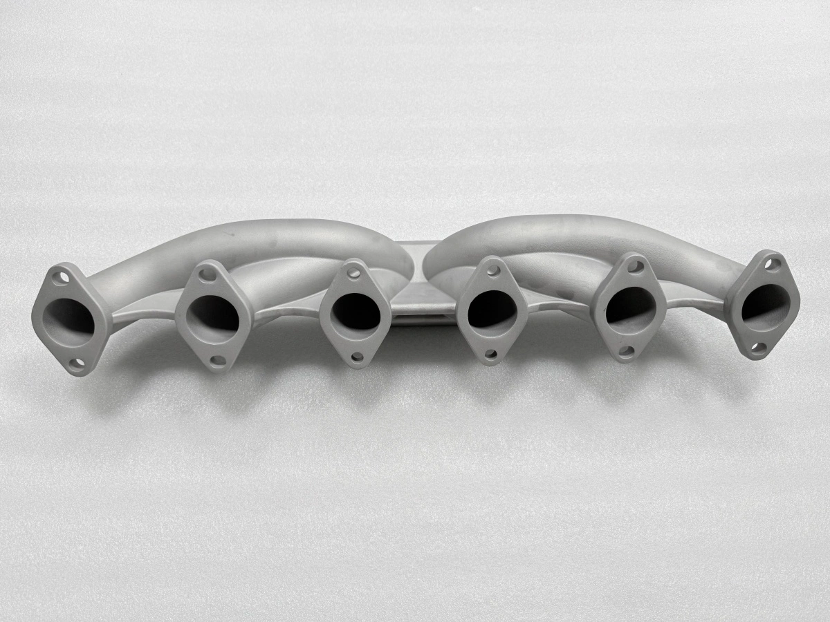
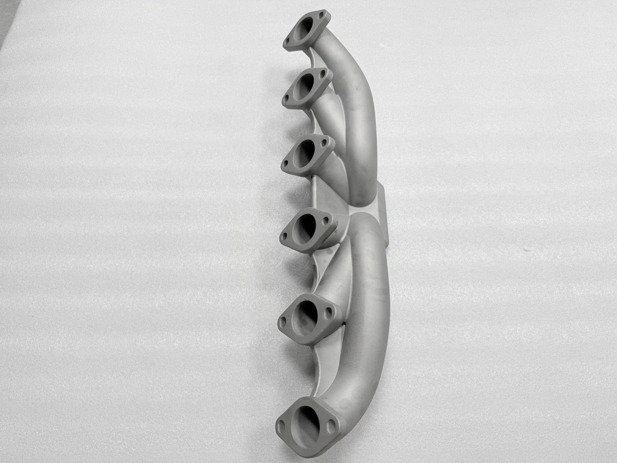
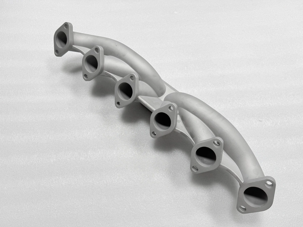
A cast stainless exhaust manifold with 2.5 mm walls machines cleanly when three conditions hold: the six faces keep 1.5 mm of stock, the part is stress-relieved at 880 °C for 3 h and furnace-cooled to 200 °C, and the finishing passes stay at 0.4 mm axial depth. Take any one away and the flatness that measured 0.05 mm on the bench moves after the part sits overnight. The machining problem on this part is not hardness; it is the skin and the residual stress underneath it.
What machinability means for a cast exhaust manifold
Machinability on a casting is usually described as a cutting-speed number, and that number is close to useless here. A cast stainless manifold arrives with a mold skin on every surface, a wall that varies between 2.5 mm and 4 mm depending on the runner, and a stress field left over from cooling. The cut has to survive the skin, avoid pushing the thin wall, and leave enough material for the relief to work on.
The three properties that actually decide the cut are stock uniformity, skin condition and stress state. Stock uniformity sets how many passes are needed before the face is clean; a face that varies by 0.4 mm around the flange needs a roughing pass and a semi-finish before any finishing pass can be trusted. Skin condition sets the first cut: a sand-blasted casting at Ra 3.2–6.4 µm cuts differently from a shell that still carries ceramic residue, because the residue dulls an insert within a few centimeters.
Stress state sets the last cut. A casting that has not been relieved will move after the finishing pass, and the movement is not visible until the part is unclamped. That is why the sequence on this manifold puts relief before machining rather than after, and why the 24 h re-measurement sits between them.
Shrinkage and skin: where the first cut lands
Shrinkage has already been paid for before the casting arrives: the cavity carried 2.2% compensation, so the faces come in with 1.5 mm of stock rather than a nominal surface. What the machinist inherits is the scatter around that figure. On a manifold the six faces do not carry identical stock, because the sections behind them freeze at different times, and the difference can reach 0.3 mm across a pair of faces.
The first cut therefore lands on the highest face, not on the average. Taking 0.5 mm off the high face and 0.2 mm off the low one keeps the datum intact; taking a uniform 0.3 mm off both leaves the low face uncut and forces a second setup to chase it. The pattern quality behind that scatter is set earlier, in precision wax pattern creation, and shows up here as stock variation rather than as a defect.
Skin matters for a second reason. The as-cast skin on stainless is work-hardened and slightly decarburized at the surface, so the first 0.2 mm cuts harder than the material underneath. Inserts that are happy in the core will chip on the skin, and a chipped insert on a 2.5 mm wall is a scrapped part. Blasting the faces to Ra 3.2–6.4 µm before machining removes the worst of the skin and makes the first pass predictable.
Stress relief at 880 °C and why 24 h matters
Relief runs at 880 °C for 3 h, followed by a furnace cool to 200 °C before the part is taken out. The soak temperature is chosen to relax the residual stress from casting without altering the cast structure; the furnace cool is chosen because pulling the part at 880 °C and cooling it in air puts a new gradient across the flanges, which is the same mechanism the relief was meant to remove.
The 24 h figure is a measurement window, not a process step. A part that has just come through a 3 h soak is still settling as it reaches room temperature, and measuring it two hours after the door opens gives a datum that will have moved by the time the first cut is taken. Re-measuring within 24 h, and using that reading as the datum, is what makes the first cut land where the drawing expects it.
The relief sequence is run on the heat treatment line, and the mechanics behind it are set out in stress relief in castings. The check that follows is a flatness reading on a surface plate, not a CMM scan: a plate shows a rocking face immediately, which is the failure this step is meant to prevent.
Cutting parameters that hold 0.05 mm flatness
Roughing runs at 600–1500 r/min with a 0.8 mm depth of cut and a feed of 300–500 mm/min, and it is deliberately kept conservative on the thin sections. The wall behind a runner face is 2.5 mm, and a heavy radial cut on a face backed by 2.5 mm of metal will deflect the wall before it cuts, which shows up later as a flatness error rather than as a chatter mark.
Finishing runs at 1500–2000 r/min with 0.4 mm axial depth and the same 300–500 mm/min feed. The 0.4 mm figure is the one that holds the 0.05 mm flatness: a deeper finish pass stores enough energy in the thin wall to spring back after the insert passes, and the face reads concave on the plate. Two 0.4 mm passes cost less time than one 0.8 mm pass plus a re-cut.
Operation | Spindle speed | Feed | Depth of cut | Result held |
|---|---|---|---|---|
Roughing, faces | 600–1500 r/min | 300–500 mm/min | 0.8 mm radial | Stock evened to 0.6 mm |
Semi-finish | 1200–1800 r/min | 300–500 mm/min | 0.5 mm axial | 0.1 mm stock left |
Finishing, sealing faces | 1500–2000 r/min | 300–500 mm/min | 0.4 mm axial | Flatness ≤0.05 mm |
Thread milling, M10×1.5 | 800–1200 r/min | 100–200 mm/min | Full profile | Engagement ≥1.5×D |
The table is the cutting side of the process card. Every number in it assumes the relief has already run: the same parameters on an unrelieved casting will hold flatness for an hour and then lose it overnight.
Surface finish and thread quality on cast stainless
Sealing faces finish to Ra ≤1.6 µm, which is achievable in one 0.4 mm pass if the semi-finish left 0.1 mm and the insert is fresh. Chasing Ra 0.8 on a cast surface by slowing the feed usually makes the finish worse, because the insert rubs the work-hardened skin instead of cutting it; the fix is a lighter axial depth, not a slower feed.
Threads on this part are M10×1.5 in the flange corners, and the specification calls for engagement of at least 1.5×D. On a casting that means checking two things: the hole is not drilled into a shrinkage porosity pocket, and the thread is formed or milled rather than tapped into a hard spot. Thread milling holds the pitch diameter more consistently than tapping on cast stainless, and it lets a go/no-go gauge be used on every hole rather than on a sample.
The finish measurements and the flatness readings are collected against the dimensional control limits, and the casting behind them is accepted to CT6 under ISO 8062-3. The machining side of the same process is run by the CNC machining team, and the setup logic is described in CNC machining on castings.
Where cast stainless stops paying off
The first comparison is against a welded fabrication. A welded stainless manifold is cheaper below roughly 100 parts and needs no tooling, but every weld is a heat-affected zone that moves after machining, and the flange flatness on a welded part depends on the fixture rather than on the parent metal. Casting wins when the geometry repeats, when the wall is thin enough that welding distorts it, and when flange flatness has to survive a thermal cycle.
The second comparison is against a printed part. Printing wins when the geometry is still moving, when the part count is under about 30, and when the wall can be thickened for the process; it loses when the surface has to be Ra ≤1.6 µm on six faces, when the part has to be produced at a rate the printer cannot match, and when cost per part matters more than lead time.
Cast stainless stops paying off when the wall drops below 2 mm with a cored internal passage, when the alloy is a grade that cannot be cast cleanly at this section, or when the quantity never reaches the point where the tooling amortises. In those cases the honest answer is a different route, not a better machining plan.
The material side of that boundary is not settled by a machining test. As-cast chemistry and structure are covered by equiaxed crystal casting, certificates come from the material testing and analysis line, and the production sequence on a comparable part is set out in stainless steel casting production. This article covers machining conditions only; it makes no claim about a specific grade, and it does not cover weld repair or hot isostatic pressing.
Send the drawing with the six flange faces and the alloy, and we will return the stock call, the relief window and the cutting parameters that fit the wall, priced with the vacuum investment casting route alongside the machining. If the wall or the quantity says a different route, we will say that instead.
FAQs