Exhaust Manifold Process Selection: 3 Routes, One Part
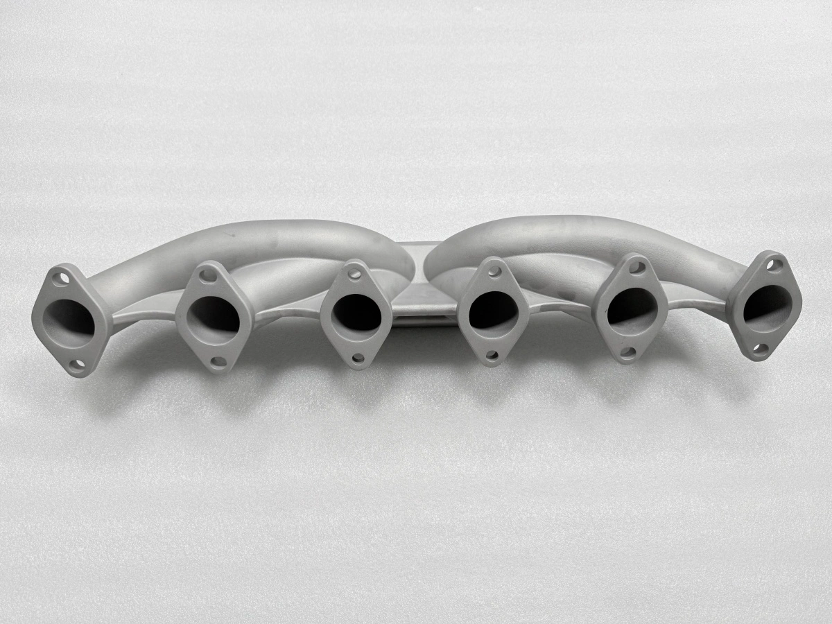
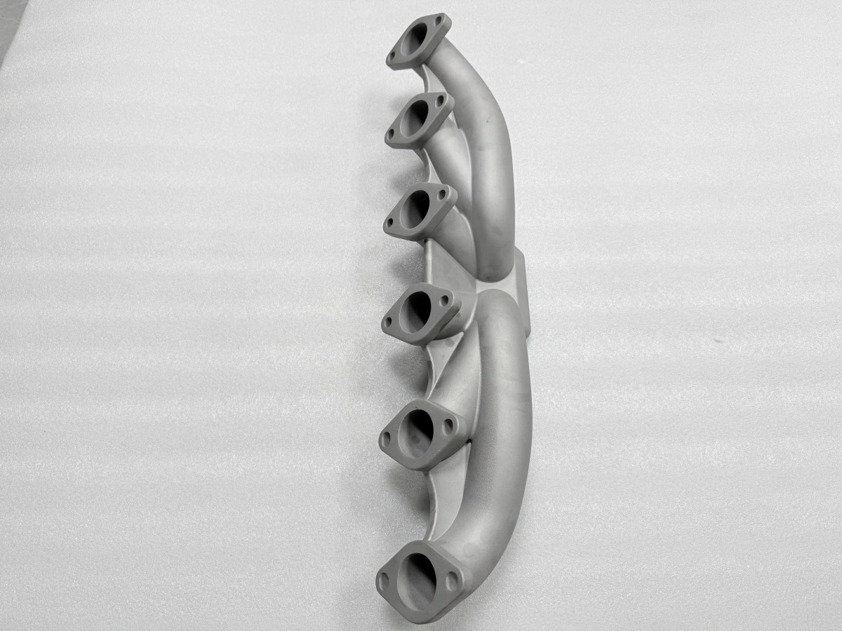
Exhaust manifold process selection is decided by four inputs, not by a preference for one shop: whether the design is frozen, how many parts the batch holds, how thin the wall runs and what the data will be used for. Three routes answer those inputs differently, and this manifold has been built on all three.
Which manifold route survives design freeze?
Design freeze decides first, because a route that cuts a cavity cannot absorb a geometry change. A frozen model with an ECO record can go to hard tooling, where the cavity is built once and repeats for the life of the programme. An open model cannot, because a change moves the runner centre, the flange face and the port position together, and the tool carries that error into every part.
The three routes absorb a change at very different speeds, and the spread is wide enough to settle the argument. Printed metal re-slices and reprints this manifold in about 1 day with no tool touched. A printed wax pattern takes about 2 days for a new model, then the normal 12-day shell and pour. A hard tool has to be recut, which runs about 6 weeks for a 4-cavity tool plus the first article.
That spread turns design freeze into a cost, and the cost is easy to read on a schedule. One day of change is affordable during development, two days are tolerable, and six weeks force the programme to wait. This is why the route sequence on a new manifold usually runs print, then printed wax, then tooling: the first two routes buy iterations, and the third buys repetition.
There is a second reason to start on the printed route. A printed part proves fit, port alignment and bracket clearance within about 4 days of a model release, so the geometry questions are closed before the casting process is reviewed. Freezing a design that has never been on a bench is the expensive version of design freeze.
What batch size changes the answer?
Batch size is the second input, and the break points are counts rather than opinions. From 1 to 20 parts per batch the printed metal route wins, because no cavity exists to amortise. From 21 to 299 parts the printed wax pattern wins, because the batch wants cast data but cannot carry a tool. From 300 parts upward hard tooling wins, because one 4-cavity tool spreads across the batch and the price per part falls below both printed routes.
The arithmetic behind those bands is the tool, and the tool does not scale with the order. A 4-cavity tool carries design, cavity cutting, parting lines, ejectors and a first article, and none of that changes when the quantity changes. Below 300 parts the tool price sits on too few parts and the per-part cost stays high; above it, the same tool pays for itself inside the first batch.
Two habits keep the batch decision honest. The first is to quote the job split into four lines, tool, part, post-processing and inspection, because a single piece price hides the tool and makes the first order look cheaper than the repeat. The second is to count the annual quantity before the cavity is cut, because a tool ordered for a test volume is a tool that never amortises.
The bands are estimates of where a break point sits, not a rule from a standards body, and a project near a boundary should ask for both quotes side by side. The tolerance does not enter this decision: this manifold is held to CT6 under ISO 8062-3 whichever route makes it, so the batch choice moves cost and lead time, not the inspection standard.
How do the three routes differ in the first week?
In the first week the routes look least alike, and the difference is visible in what each one is waiting for. Printed metal is printing by day two, having spent about a day in model preparation and slicing. The superalloy 3D printing route then needs support removal, cleaning and stress relief, which lands the part near day four.
The wax pattern 3D printing route spends its first days on the pattern and then disappears into the vacuum investment casting chain. A 7-layer shell dries about 8 h per layer, the pour runs at 1600 °C after burnout, and the first article arrives around day 14. Nothing in that chain can be compressed by working harder, because the drying time is set by the ceramic.
Hard tooling spends its first week on drawings and cavity design. The precision wax pattern that defines the cavity is still a design document at that point, and the automatic wax press is being booked rather than run. The first part from a tool arrives around week eight, which is why the tool is scheduled against the production date and not the test date.
Read that way, the first week is a preview of the whole programme. A route that is printing on day two will be printing on every iteration, and a route that is cutting a cavity in week one will be cutting cavities for the rest of the year. The second week repeats it: the printed part is already machined and checked while the casting is still coming out of the shell.
Where does a 2.5 mm wall stop a route?
A 2.5 mm wall runs on all three routes, so the wall is not the deciding input for this part; it becomes deciding when the drawing thins. Printed metal reaches down to about 0.8 mm before support and distortion dominate, while both casting routes stop near 2.0 mm because the metal loses heat before it reaches the far end of a long runner.
The failure mode explains the limit better than the number. In a casting, a thin wall fails as a cold shut at the last cavity to fill, and the gating system can fix it only up to a point. On the printed route, a thin wall fails as distortion and as a support scar that cannot be machined away. Both are wall problems, but only one of them is solved by pouring hotter.
The precision pouring side of the argument is worth stating plainly. A 1600 °C pour into a 7-layer shell fills 2.5 mm reliably, and below 1.5 mm the same geometry becomes a research problem rather than a production route. A printed part at 1.0 mm says nothing about whether a casting can fill it, so the wall check belongs to the route under consideration, not to the last part that was made.
Which route carries production data?
Only the two casting routes carry data that transfers to production, and they carry it because they share one chain. A wax pattern feeds the shell, the pour and the heat treat exactly as a hard tool does, so a part made from a printed wax pattern inherits the casting state the series will run. Printed metal does not, because a laser melt has a different grain, a different skin and a different residual stress field.
The numbers behind that difference are concrete. A printed manifold is stress relieved at 800 °C for 1.5 h after support removal and keeps 1.0 mm of allowance, while a casting is relieved at 880 °C for 3 h after cleaning and keeps 1.5 mm. Those are two different starting points for the same superalloy CNC machining sequence, and only one of them describes the part that will ship.
The practical consequence is a small, cheap test rather than a large, expensive one. One wax-pattern part, poured and heat treated like production and measured against the drawing, proves that the gating fills the wall, that the shrinkage compensation sits in the right direction and that the stress relief in castings leaves the flange flat enough to machine.
The record that comes with the part matters as much as the test. A single wax-pattern casting carries a dimensional report at CT6 under ISO 8062-3. It also carries a 3D scan against the model at an acceptance band of ±0.9 mm. That pair is the smallest evidence set a production route can inherit.
That test is also the cheapest way to fail early. A casting that will not fill, or a flange that will not clean up, is better found on one part in week two than on a cavity in week eight, and the stainless steel casting case is the shape of that sequence in practice.
When is printing the wrong answer?
Printing is the wrong answer as soon as the question stops being geometric. A printed part proves shape, fit and clearance, and it proves nothing about casting behaviour, machining stock or the metallurgy that a customer may require in a material certificate. Asking a printed part to answer those questions produces a confident answer that later fails at the first casting.
The second wrong answer is printing into a volume. Printed metal holds to about 20 parts and printed wax to about 299 before the per-part price passes a tool, and pushing either route past that band is a decision to pay more for less. The route that carries 300 parts at one price is the one with a cavity in it. An evaluation that mixes printed and casting results approves the wrong route.
The CNC machining of castings step is where these choices become visible. A casting that arrives with 1.5 mm of allowance machines like the drawing; a casting that arrives with black skin becomes a repair, and a printed part that arrives with a support scar becomes a different kind of repair. The route decides which of the three the machinist meets.
Send the drawing with the design freeze status, the annual quantity and the test date, and the answer comes back with the route that fits all three, plus the point where a faster route stops being the cheaper one. No price is quoted before those three inputs are on the table.
FAQs