Which Exhaust Manifold Route Holds Flange Flatness?
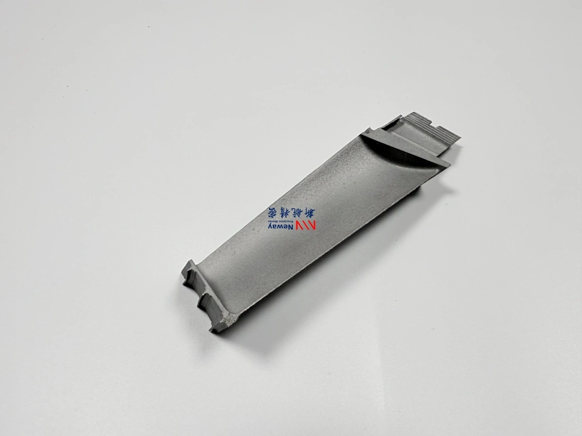
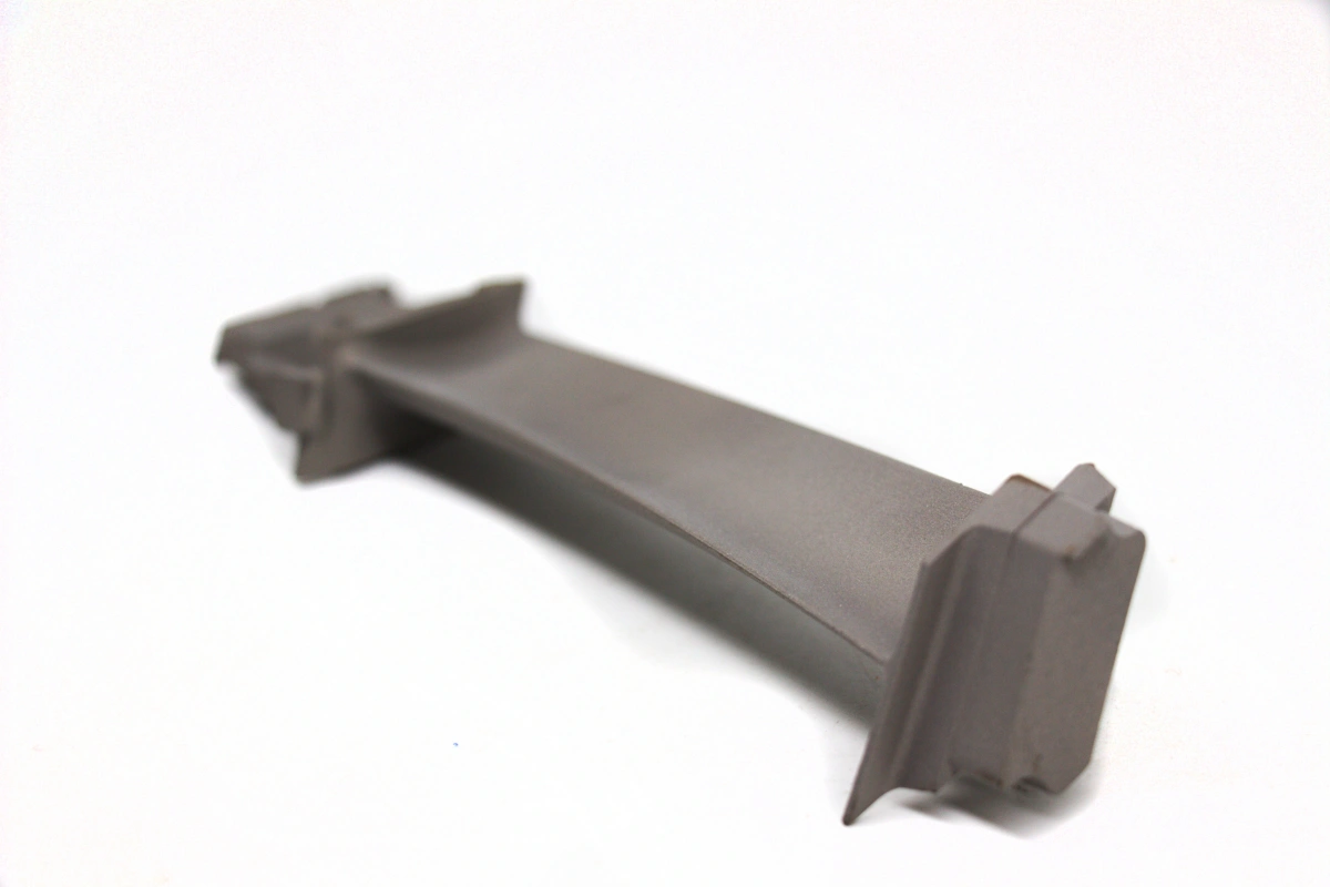
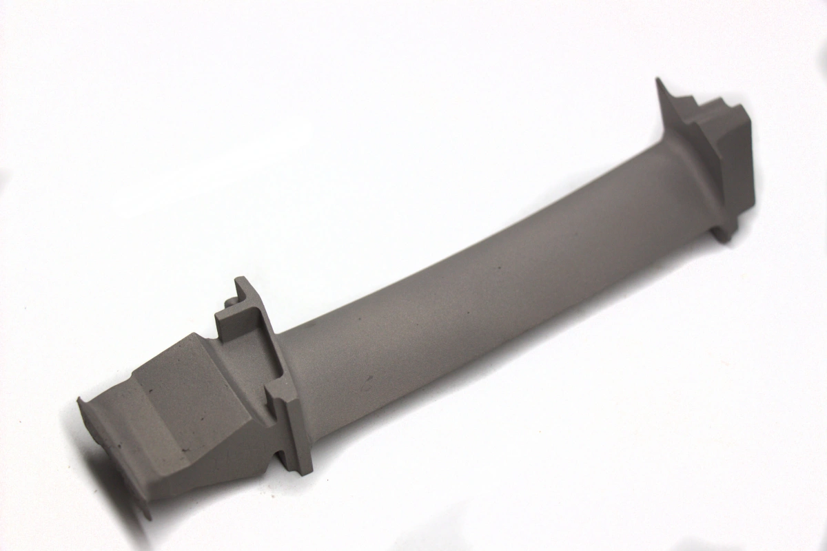
Exhaust manifold flange flatness reaches 0.05 mm on all three manufacturing routes, and the number is held by the machining allowance, not by the process that made the blank. A casting needs 1.5 mm of allowance on six runner faces and the turbo flange; a printed part needs 1.0 mm. Give the cutter less than that and flatness becomes a repair job.
How much exhaust manifold flange flatness can each route hold?
Each route holds 0.05 mm after machining, and the routes differ in how much stock they leave for it. Printed metal comes off the machine at 1.0 mm allowance because the near-net shape is tight and the flange face is already close to drawing. Both vacuum investment casting routes leave 1.5 mm because a cast surface carries draft, skin and distortion that have to be cut away.
The 0.05 mm flatness figure is the same on all three because it is set by the machine, not by the blank. A three-setup sequence takes the six runner faces and the turbo flange from rough to finish, and the fixture and the cutting strategy decide whether 0.05 mm is reached. What the route decides is whether the cutter finds metal on the first pass.
Why does a casting need more allowance?
A casting needs 1.5 mm because the cast face is not where the drawing puts it. Shrinkage moves the face, the shell adds a skin that has to be removed, and the parting line can sit slightly proud of the nominal surface. With 1.0 mm of allowance, the first cut on this manifold left black skin on two runner faces and the operation became a blend instead of a face.
The printed route escapes that problem because it has no shell and no parting line. Its 1.0 mm allowance covers the support scar and the small distortion left after stress relief, and nothing more is needed. Copying the casting allowance onto a printed part wastes 15 minutes of roughing per face; copying the printed allowance onto a casting leaves black skin.
How are six flange faces machined flat?
Six runner faces plus one turbo flange are machined in a three-setup machining sequence, and the order carries the flatness. Setup one holds the turbo flange and faces three runners at a time; setup two turns the part and faces the other three; setup three finishes the turbo flange and the sealing faces at the same setting.
The superalloy CNC machining sequence runs rough, semi-finish and finish with a 0.8 mm radial step-down and a 0.3 mm finish pass, and the clamp pressure stays under 1.0 MPa so the thin flange does not spring back after unclamping. Flatness is measured after the part has sat for 24 h, not straight off the machine.
What moves exhaust manifold flange flatness after machining?
Two things move flatness after the cutter leaves: residual stress and clamping. A casting that was never stress relieved will bow as material is removed from one side only, and this manifold is relieved at 880 °C for 3 h precisely to move that distortion before the finish pass.
Clamping is the second mover. A 2.5 mm wall flange deflects under a stiff clamp and springs back when the vice opens, which is why the finishing pass runs at low pressure and why the faces are checked on a dimensional control program that includes a free-state measurement. A face that reads 0.05 mm in the vice and 0.09 mm free is a clamp problem, not a cutter problem.
When does a route stop holding the flatness?
A route stops holding flatness when the blank cannot feed the cutter, and that limit arrives at different points. A casting below 1.2 mm allowance on this flange geometry cannot be faced clean without breaking into the skin, and a printed part below 0.8 mm starts to scrape the support scar instead of cutting it.
The other limit is the wall itself. A turbo flange thinner than 2.5 mm distorts under the heat of machining and under the bolt load that follows, and no allowance fixes that; it needs a design change. The tolerance behind the number stays CT6 under ISO 8062-3 for all three routes, so the inspection standard never changes with the process.
Send the drawing with the flange callouts and the flatness target, and the answer comes back with the allowance that route needs and the three-setup sequence that reaches 0.05 mm on this geometry.