
Exhaust Manifold Casting Shrinkage: 2.0% Failed, 2.2% Held
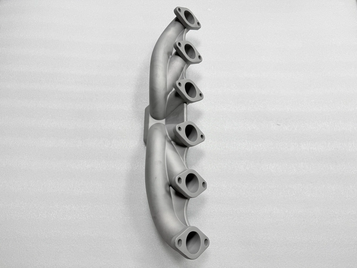
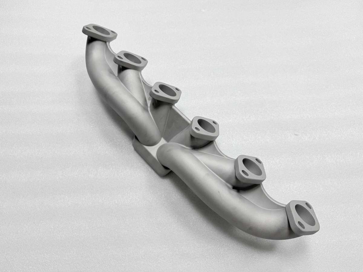
Exhaust manifold casting shrinkage does not follow one number, because a thin-wall manifold shrinks in three stages that do not add up to a single scale factor. Liquid contraction, solidification contraction and solid cooling each act on a different section of the same part. On this manifold a flat 2.0% allowance left the first article 0.4 mm small overall, while 2.2% plus a 0.2 mm local cavity correction held the batch inside ±0.15 mm.
Why exhaust manifold castings shrink in three stages
The first stage is liquid contraction. As the metal cools from the pour at 1600 °C to its liquidus, the volume drops without any shape change, and the feeder has to replace that loss. The second stage is solidification: the skin forms while the center is still liquid, and the last liquid to freeze has nowhere to draw from, which is where a 2.5 mm wall either feeds or shrinks away from the mold face.
The third stage is solid contraction, and it is the one the patternmaker's shrink rule is meant to cover. A rule that adds a single percentage to every dimension assumes the first two stages are invisible at room temperature. On a manifold they are not: the runner section freezes before the flange, so the flange is still shrinking while the runner has stopped, and the difference ends up as a displacement between the flange faces rather than as a uniform size change.
That is why the same 2.2% that works on the body can be wrong on a flange face. The number is not a property of the alloy alone; it is a property of the alloy, the section and the local thermal gradient together.
Feeder sizing follows from that. A feeder that is large enough for the flange is oversized for the runner and leaves a heavier section that cools last, so the two ends of the part freeze on different clocks. The workable compromise is a feeder sized on the thickest section and a cavity scale that is checked on the thinnest one, which is why the first article is measured at both ends rather than at one.
Why thin walls and thick flanges move differently
A 2.5 mm wall freezes in seconds and then contracts as a solid body with little support from the feeder. A flange that is 8 mm thick stays liquid longer, draws metal from the feeder, and shrinks more in absolute terms while shrinking less per unit length. Compensating both with one scale factor over-corrects one and under-corrects the other, and the error shows up as a mismatch rather than as a size error.
The practical consequence is that shrinkage compensation is applied in two moves. First the global scale, which handles the third stage across the part. Then a local cavity correction on the faces where the measured first article disagrees with the model, which handles the first two stages where they matter. On this manifold the global figure ended at 2.2%, and the local cavity correction was 0.2 mm on two flange faces.
Measured on the same part, the body length moved by 0.1 mm between the two allowances while the flange centers moved by 0.4 mm. The difference is the section effect: one dimension is dominated by solid contraction, the other by the earlier stages, and a single scale cannot serve both. That is the reason the compensation figure is quoted with the faces it applies to, not as a single percentage for the whole part.
Control lever | Casting route | Additive pattern route |
|---|---|---|
Shrinkage handled by | Cavity scale plus local cavity correction | Scale applied in the print file |
First-article tool | Wax pattern measured on a CMM | Printed pattern measured on a CMM |
Correction window | Cavity re-cut, measured in days | File re-issued, measured in hours |
Batch consistency | Cavity wear tracked per batch | Build-to-build variation per print |
Best fit | Volume above roughly 300 parts | Frozen geometry, prototype volumes |
The table matters because the two routes control the same physics with different levers: the casting route corrects a cavity, the additive route corrects a file. Neither removes the first-article loop. A printed pattern is covered in wax pattern 3D printing.
The first-article loop: measure, correct the cavity, re-pour
The loop starts with a measured first article, not with a drawing. On this manifold the pattern was measured at the six flange centers and the body length, against a CAD model carrying the 2.2% scale. The result was 0.4 mm small in the first trial at 2.0%, which is too large to absorb with machining stock and too uniform to be a pouring problem.
The correction went into the cavity, not into the press. Two faces were re-cut by 0.2 mm and the next three patterns confirmed the correction before the batch ran. That is the whole loop: measure the pattern, correct the cavity by the measured amount, pour again, and only then release the batch. A correction made on the press instead would have moved the defect rather than removing it.
The acceptance figure for the loop is the batch band, not a single part. Here the band is ±0.15 mm on the flange centers, checked against the dimensional control limits used for the finished casting rather than against the drawing limits. A band of ±0.15 mm sounds tight until it is compared with the 1.5 mm machining stock: the band is what protects the stock, and the stock is what decides whether the part can still be machined after 300 pieces.
Why stress relief comes before finish machining
A casting that has cooled in the mold carries residual stress from the same thermal gradient that caused the uneven shrinkage. Machining removes the material that was holding that stress in balance, and the part moves. On this manifold the relief runs at 880 °C for 3 h, then a furnace cool to 200 °C before the part is taken out.
The datum is re-measured within 24 h of the relief, because a part that has just come through a 3 h soak is still settling. Flatness after machining is held at 0.05 mm on each sealing face, and it only stays there if the relief happened first. Skip it and the flange moves 0.1 mm in the third week of machining, which is the failure mode set out in stress relief in castings.
The furnace cool is part of the cycle rather than a convenience. Taking the part out at 880 °C and letting it cool in air reintroduces a gradient across the flanges, which is the same mechanism the relief was meant to remove. Cooling to 200 °C inside the furnace costs hours and buys a part whose datum does not move after the first cut.
The heat treatment route for the relief is run on the heat treatment line, and the vacuum cycle used on superalloy grades is described in stress relief in superalloy castings.
Where shrinkage compensation stops working
Compensation stops working when the defect is no longer dimensional. A misrun, a cold shut or a gas defect cannot be scaled out of a cavity; changing the compensation to chase them makes the dimensional problem worse while leaving the filling problem intact. The boundary is that line: compensation fixes size, and it does not fix filling.
It also stops working without a first-article loop. A batch run on an unverified cavity has no reference for the correction, and the ±0.15 mm band is a claim that has to be measured rather than assumed. Below roughly 300 parts the loop usually costs more than the parts are worth, and a printed pattern is the cheaper way to hold the geometry until the design stops moving. That is a cost boundary, not a technical one: the loop still works, it just cannot be amortised over a small order.
There is also a geometry boundary. When a flange is thin enough that the relief itself distorts it, compensation stops being the lever and the fixture becomes one; at that point the part is held in a stressed fixture through machining rather than being corrected in the cavity.
The third boundary is the material claim. A dimensional report and a CT6 drawing tolerance under ISO 8062-3 say nothing about fatigue life, pressure tightness or customer acceptance. Testing for those sits on the material testing and analysis side, and the metallurgical background for equiaxed structures is covered in equiaxed crystal casting. A production case on stainless steel casting production shows the same loop running on a comparable part.
Send the drawing and the alloy, and we will return the compensation figure, the local cavity corrections it implies and the first-article plan that proves them, priced with the vacuum investment casting route before the cavity is cut.
FAQs