Vacuum Casting and CNC Machining Challenges for Inconel 713LC NGV2 Components
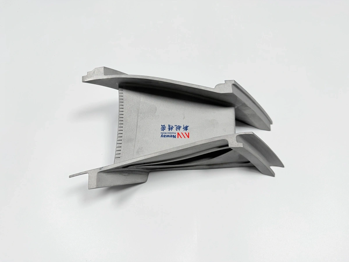
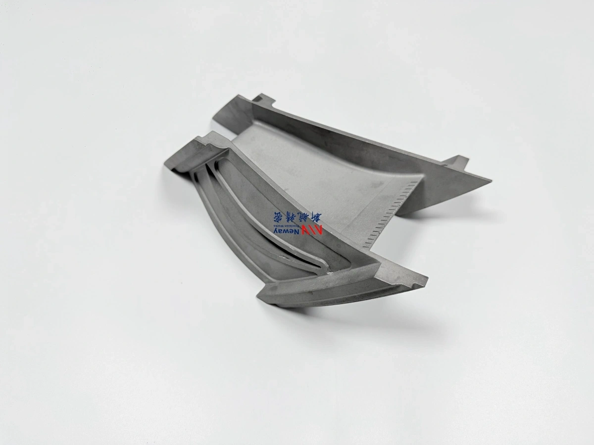
Inconel 713LC NGV2 components are critical hot-section parts used in small turbojet, small turbofan, UAV, and UCAV turbine engines. NGV2 usually refers to a Nozzle Guide Vane Stage 2 or second-stage nozzle guide vane, which controls the direction, velocity, and pressure distribution of high-temperature gas before it enters the next turbine rotor stage.
Compared with large industrial turbine vanes, UAV engine NGV2 components are often smaller, thinner, and more sensitive to airfoil profile deviation. Their compact geometry creates major challenges in Vacuum Investment Castings, CNC machining, airfoil inspection, and final quality verification.
For Inconel 713LC NGV2 manufacturing, the key difficulty is not only producing the casting blank. The real challenge is maintaining the airfoil profile, throat area, platform height, sealing interface, and mounting accuracy after vacuum casting and Superalloy CNC Machining.
Why NGV2 Geometry Is Difficult to Manufacture
NGV2 components are small, aerodynamic, and exposed to high thermal loads. Their geometry usually includes thin leading edges, thin trailing edges, curved airfoil surfaces, compact platforms, narrow flow passages, and tight assembly interfaces. Even a small deviation in the vane profile may affect gas flow direction, turbine efficiency, and stage matching.
NGV2 Feature | Manufacturing Challenge | Potential Risk |
|---|---|---|
Thin leading edge | Easy to deform during casting or machining | Airflow disturbance, local overheating |
Thin trailing edge | Difficult to fill and easy to chip | Profile deviation, edge damage |
Curved airfoil | Requires accurate wax pattern, casting, and inspection control | Incorrect gas flow angle |
Small platform | Limited machining and clamping space | Positioning error, vibration, distortion |
Throat area | Highly sensitive to profile and spacing variation | Reduced turbine efficiency |
This is why NGV2 components should be treated as precision hot-section parts rather than ordinary small castings. The manufacturing route must consider casting deformation, machining allowance, fixture design, inspection datum, and surface integrity at the same time.
Why Inconel 713LC Is Used for NGV2 Components
Inconel 713LC is a nickel-based cast superalloy used for high-temperature turbine components, including nozzle guide vanes, turbine vanes, and other hot-section static parts. It offers a strong balance of high-temperature strength, oxidation resistance, and casting suitability for complex small turbine geometries.
For UAV and UCAV turbine engines, Inconel 713LC is often selected when the component must withstand high-temperature gas flow, thermal cycling, oxidation, and mechanical stress while still allowing near-net-shape casting. Related material capabilities can be supported through Inconel alloy vacuum investment casting and broader Superalloys manufacturing.
Vacuum Casting Challenges for Inconel 713LC NGV2 Parts
Vacuum casting is suitable for NGV2 parts because it can form complex airfoils, platforms, thin edges, and near-net-shape hot-section geometry. However, the small size and thin-wall structure of NGV2 components make casting control difficult.
1. Wax Pattern Deformation
The airfoil profile of NGV2 parts starts from the wax pattern. If the wax pattern deforms before shell building, the final casting may already contain profile deviation. For small aero engine NGV2 components, even minor wax distortion can affect the throat area and flow passage consistency.
2. Ceramic Shell Strength and Dimensional Stability
The ceramic shell must support thin airfoils and small platforms during burnout and pouring. Insufficient shell strength may cause deformation, while poor shell control may affect airfoil surface quality and dimensional repeatability.
3. Thin-Wall Filling
NGV2 leading edges, trailing edges, and thin airfoil sections require stable metal flow. Incomplete filling can lead to short runs, cold shuts, or weak edge formation. This is especially important for Inconel 713LC because pouring temperature, mold temperature, and flow path design must be controlled carefully.
4. Shrinkage, Porosity, and Hot Tearing
Small turbine vanes may contain local thickness transitions between the airfoil and platform. These areas are sensitive to shrinkage porosity, gas porosity, and hot tearing. The gating system, feeding design, and solidification path must be planned to reduce internal defects.
5. Grain and Microstructure Control
NGV2 components used in hot-section environments require stable microstructure and consistent high-temperature performance. For static vane components, Equiaxed Crystal Casting is commonly considered when the component requires cast superalloy performance without single-crystal or directional-solidification requirements.
Machining Allowance Strategy After Casting
Vacuum casting creates the near-net-shape NGV2 blank, but CNC machining is still required for precision mounting surfaces, platform boundaries, sealing interfaces, holes, slots, and datum features. The machining allowance must be planned before casting.
Too little allowance may leave casting skin, local deformation, or surface defects on critical surfaces. Too much allowance can increase machining time, tool wear, and risk of thin-wall distortion. For Inconel 713LC NGV2 components, the allowance strategy should consider three factors:
casting shrinkage and expected deformation;
machining datum and fixture location;
final inspection datum and airfoil profile requirements.
A strong NGV2 manufacturing plan keeps casting datum, machining datum, and inspection datum aligned. This reduces cumulative error and improves consistency between cast geometry, machined interfaces, and final airfoil inspection results.
CNC Machining Challenges for Inconel 713LC Vanes
Inconel 713LC is difficult to machine because it retains strength at elevated temperatures and can accelerate tool wear. For small NGV2 parts, CNC machining is even more challenging because the component is thin, compact, and difficult to clamp without distortion.
1. Tool Wear and Cutting Heat
Nickel-based superalloys generate high cutting forces and heat during machining. Tool wear must be controlled to avoid poor surface finish, dimensional drift, burrs, and edge damage.
2. Thin-Wall Vibration
NGV2 airfoils and platforms may vibrate during machining if the fixture does not support the part correctly. Vibration can cause chatter marks, profile deviation, and local surface damage.
3. Clamping Distortion
Because NGV2 components are small and thin, excessive clamping force may distort the casting during machining. Once released from the fixture, the part may spring back and fall outside tolerance.
4. Burr Control
Burrs on platform edges, mounting holes, sealing faces, or flow-path boundaries can affect assembly and airflow. Burr control is especially important near leading edges, trailing edges, and small openings.
5. Datum Consistency
The machined datum must match the inspection strategy. If machining and inspection datums are not aligned, the part may pass one inspection step but fail final assembly or airfoil profile verification.
When EDM May Be Required
Some NGV2 designs include small holes, narrow slots, sharp internal corners, or local features that are difficult to machine with conventional cutting tools. In such cases, Superalloy Electrical Discharge Machining EDM may be used as a supplementary process.
EDM is useful for hard superalloy components because it does not rely on traditional cutting force. However, EDM features must still be controlled for recast layer, microcracks, edge condition, and surface finish before final inspection or service use.
Airfoil Profile and Throat Area Inspection
For NGV2 components, airfoil profile control is one of the most important quality requirements. The vane does not only need to fit mechanically; it must also guide gas flow correctly.
Inspection should focus on the following features:
Inspection Item | Purpose |
|---|---|
Airfoil profile | Confirms the vane surface matches aerodynamic design |
Leading edge and trailing edge | Checks thickness, contour, and edge integrity |
Throat area | Verifies gas flow passage consistency |
Platform height | Ensures correct assembly and flow-path alignment |
Mounting and sealing surfaces | Confirms fit with engine housing or adjacent components |
Hole and slot position | Ensures assembly and functional features are accurate |
CMM inspection, profile scanning, optical measurement, and dedicated fixtures may be required depending on the tolerance level and engine application. For aerospace hot-section parts, inspection should also include material and defect verification through Superalloy Material Testing and Analysis.
Surface and Edge Quality Control
Surface and edge quality are critical for small turbine NGV2 components. Sharp burrs, edge chips, casting fins, local cracks, or rough flow-path surfaces can affect engine performance and reduce service reliability.
Key control points include:
leading edge smoothness and thickness consistency;
trailing edge integrity without chipping;
platform edge deburring;
sealing surface flatness and finish;
hole edge condition;
flow-path surface roughness;
absence of visible cracks after casting and machining.
For small UAV engine parts, edge quality is especially important because the part size is small and airflow channels are compact. A small burr or profile mismatch may create a proportionally larger aerodynamic effect than it would in a large industrial turbine component.
Quality Documentation for Inconel 713LC NGV2 Parts
A complete NGV2 delivery package should include more than a dimensional report. For hot-section engine components, traceability and verification are essential.
Document | Purpose |
|---|---|
Material report | Confirms chemical composition and material grade |
Heat treatment record | Confirms thermal processing condition |
FAI report | Verifies first-article dimensions and key features |
Dimensional inspection report | Confirms machined dimensions and assembly interfaces |
Airfoil profile report | Confirms aerodynamic surface and throat area control |
NDT report | Checks surface cracks or internal casting defects |
Depending on the project requirements, FPI, X-ray, CT inspection, CMM measurement, metallographic analysis, and hardness testing may be added to the control plan.
Why Integrated Casting, CNC Machining, and Inspection Matter
NGV2 components require close coordination between casting, machining, and inspection. If these steps are handled separately without shared datum planning, the project can suffer from casting-to-machining mismatch, excessive machining allowance, profile deviation, or final inspection failure.
An integrated supplier can control the process from Inconel 713LC casting blank to final machined NGV2 part. This helps reduce manufacturing risk, shorten engineering feedback loops, and improve consistency across prototype and production batches.
For UAV and UCAV turbine engine projects, this integrated approach is especially valuable because small aero engine hot-section parts often require fast iteration, tight dimensional control, and reliable material performance.
RFQ Checklist for Inconel 713LC NGV2 Manufacturing
To evaluate an Inconel 713LC NGV2 project accurately, the following information is recommended:
engine type or application platform, such as UAV turbojet or small turbofan;
part name, part number, and NGV stage information;
3D model, preferably STEP or X_T format;
2D drawing with tolerances and datum definition;
material specification for Inconel 713LC;
heat treatment requirements;
coating or surface treatment requirements, if applicable;
inspection requirements, including FAI, FPI, X-ray, CT, or CMM;
prototype and production quantity;
delivery schedule and documentation requirements.
FAQ
