What Is the Function of a Nozzle Guide Vane Stage 2 in Small Aero Engines?
What Is the Function of a Nozzle Guide Vane Stage 2 in Small Aero Engines?
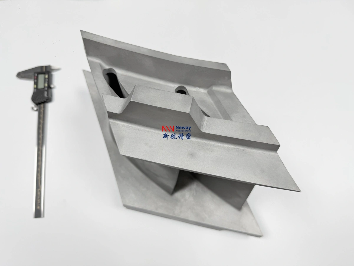
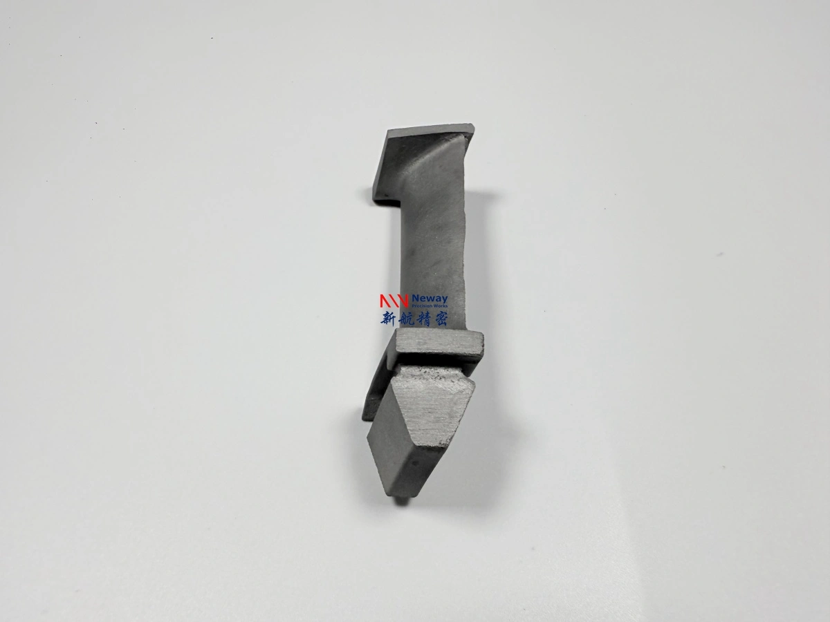
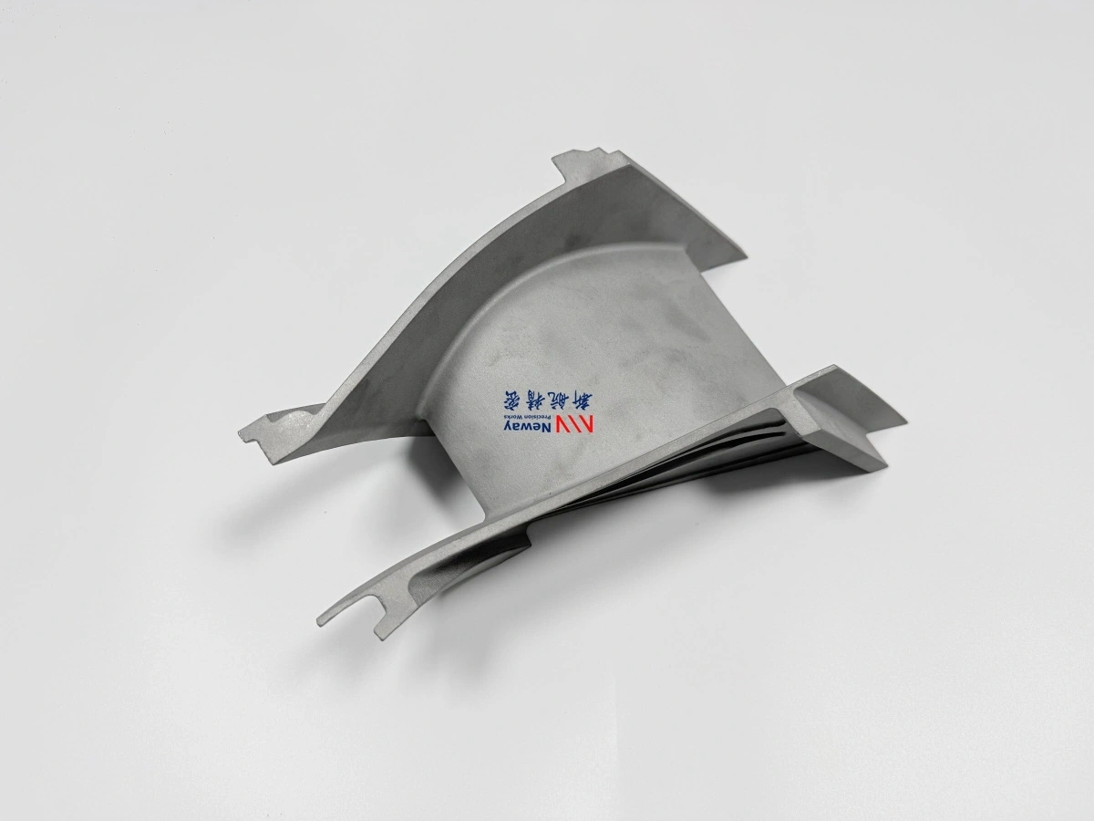
The function of a Nozzle Guide Vane Stage 2, also called NGV2 or second-stage nozzle guide vane, is to control the angle, velocity, and pressure distribution of high-temperature gas before it enters the next turbine rotor. In small aero engines, NGV2 strongly affects turbine efficiency, rotor loading, thrust response, thermal stability, and hot-section reliability.
Because NGV2 works in the turbine hot section, it must withstand high temperature, oxidation, thermal shock, vibration, and tight assembly conditions. For this reason, NGV2 components are usually manufactured from high-temperature Superalloys, then finished through precision machining, heat treatment, and inspection.
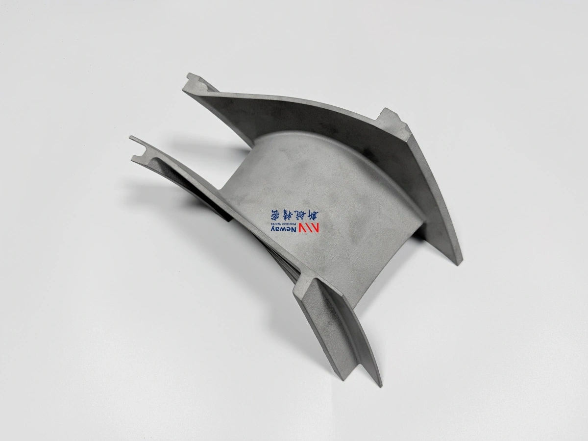
1. Direct Answer: What Does NGV2 Do?
NGV2 controls hot gas flow before the second-stage turbine rotor. It changes the direction, velocity, and pressure distribution of the gas so the downstream rotor can extract energy efficiently and operate with stable loading. If the NGV2 vane angle, throat area, or passage geometry is incorrect, the engine may suffer from reduced efficiency, unstable flow, overheating, vibration, or poor thrust response.
NGV2 Function | Engineering Purpose | Effect on Small Aero Engine Performance |
|---|---|---|
Gas angle control | Directs hot gas into the next turbine rotor at the designed flow angle. | Improves turbine energy extraction and reduces uneven rotor loading. |
Gas velocity control | Accelerates and distributes gas through controlled vane passages. | Supports rotor speed response, thrust output, and stage matching. |
Pressure distribution | Controls pressure drop and flow balance between turbine stages. | Improves turbine efficiency and helps reduce flow instability. |
Thermal protection role | Maintains structural stability under hot gas and thermal cycling. | Reduces risk of cracking, oxidation, distortion, and premature failure. |
Assembly interface | Maintains correct fit with casing, adjacent vanes, rotor clearance, and sealing features. | Prevents interference, leakage, local rubbing, and uneven thermal loading. |
2. How Does NGV2 Control Gas Flow Direction?
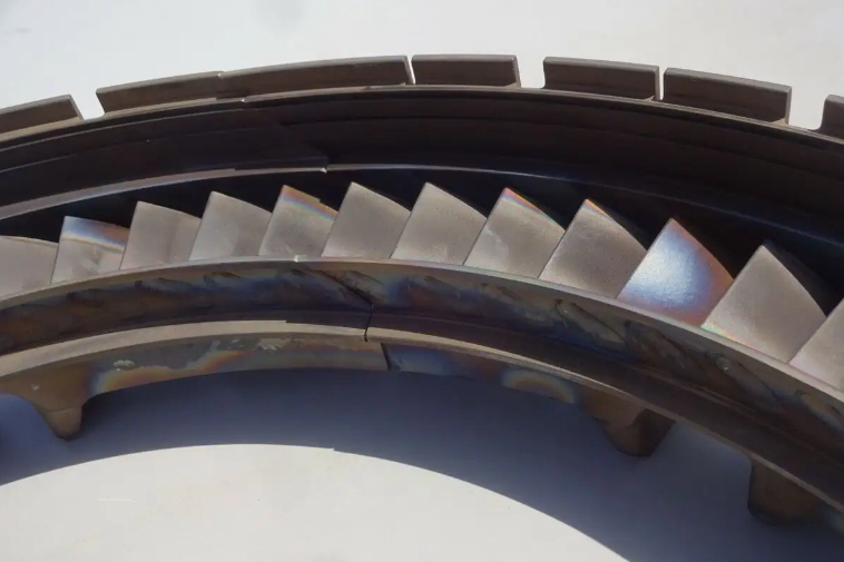
NGV2 controls gas flow direction by using fixed vane airfoils to turn high-temperature combustion gas toward the next turbine rotor. The vane profile, leading edge, trailing edge, stagger angle, and passage shape determine how the gas enters the rotor blade row.
In a small aero engine, the turbine section is compact and highly loaded. This means small errors in NGV2 vane angle or passage width can create uneven flow, local separation, rotor vibration, or efficiency loss. Accurate airfoil geometry is therefore essential for stable turbine operation.
Flow Feature | Function | Manufacturing Control |
|---|---|---|
Leading edge | Receives and turns incoming hot gas smoothly. | Controlled casting profile, edge finish, and defect inspection. |
Airfoil surface | Controls gas turning and pressure distribution. | Profile accuracy, surface finish, and 3D scanning. |
Trailing edge | Releases gas toward the rotor with the designed exit angle. | Edge thickness, straightness, cracking control, and finishing. |
Vane passage | Controls gas flow channel between adjacent vanes. | Throat width, throat area, and passage consistency inspection. |
Stagger angle | Defines the orientation of the vane relative to the engine flow path. | Tooling accuracy, casting repeatability, and fixture-based inspection. |
3. How Does NGV2 Affect Turbine Efficiency?
NGV2 affects turbine efficiency by controlling how much energy the downstream rotor can extract from the hot gas. Correct NGV2 geometry helps the rotor receive gas at the proper angle and velocity, reducing flow loss and improving stage efficiency.
For UAV turbojet, UCAV turbofan, and other compact propulsion systems, this can influence thrust, rotor speed response, fuel efficiency, exhaust temperature distribution, and overall hot-section stability. Poor NGV2 geometry can cause pressure loss, poor stage matching, local overheating, vibration, or reduced engine output.
Performance Area | How NGV2 Influences It | Possible Issue If Poorly Controlled |
|---|---|---|
Thrust output | Improves turbine energy extraction and downstream rotor performance. | Lower thrust or unstable operating response. |
Rotor speed response | Controls flow energy entering the rotor stage. | Slow response, overspeed risk, or unstable acceleration. |
Fuel efficiency | Reduces aerodynamic losses in the turbine stage. | Higher fuel consumption for the same output. |
Stage flow stability | Balances gas flow between vane passages and rotor blades. | Flow separation, vibration, or uneven rotor loading. |
Exhaust temperature distribution | Helps maintain more predictable hot gas distribution. | Local hot spots and thermal fatigue risk. |
4. What Thermal Load Does NGV2 Experience?
NGV2 operates in a severe thermal environment. It is exposed to hot combustion gas, oxidation, thermal shock, thermal gradients, vibration, and repeated heating and cooling cycles. These conditions can cause cracking, distortion, oxidation, creep-related deformation, or surface degradation if the material and manufacturing route are not properly selected.
For small aero engine hot section parts, material quality and thermal processing are critical. Superalloy Heat Treatment can help stabilize material properties, reduce process-related stress, and support high-temperature performance when required by the alloy and customer specification.
Thermal Load Factor | Effect on NGV2 | Control Method |
|---|---|---|
High gas temperature | Can reduce strength and accelerate oxidation. | Use suitable superalloy material and controlled heat treatment. |
Thermal shock | Creates rapid expansion and contraction stress. | Control material selection, wall thickness, and defect level. |
Thermal fatigue | Repeated cycles can initiate cracks at edges or stress concentration areas. | Inspect airfoil edges, fillets, casting defects, and machined transitions. |
Oxidation | Can degrade surfaces exposed to hot combustion gas. | Select oxidation-resistant superalloy and define coating if required. |
Temperature gradient | Can cause local distortion or uneven stress. | Control section thickness, casting quality, and final geometry. |
5. Why Is the Dimensional Interface Important for NGV2?
The dimensional interface of NGV2 is important because the vane must fit accurately with the engine casing, adjacent guide vanes, rotor clearance zone, sealing structure, and mounting features. Incorrect dimensions can create interference, leakage, rubbing risk, uneven expansion, or misalignment with the downstream rotor.
Superalloy CNC Machining is often required to finish mounting surfaces, datum features, sealing faces, ring interfaces, and critical holes after casting. For small turbine nozzle guide vane parts, machining datum strategy should align with aerodynamic and assembly requirements rather than only simple outer dimensions.
Interface Area | Function | Manufacturing Control |
|---|---|---|
Outer ring or casing interface | Positions the NGV2 assembly inside the turbine casing. | CNC machining, concentricity control, and CMM inspection. |
Inner ring or hub interface | Supports radial positioning and structural stability. | Datum control, roundness, and assembly-fit inspection. |
Rotor clearance area | Maintains safe spacing relative to rotating components. | Profile measurement, radial clearance check, and distortion control. |
Sealing features | Reduces unwanted gas leakage between stages or adjacent components. | Machined sealing faces, surface finish, and edge condition. |
Mounting features | Supports installation, alignment, and repeatable assembly. | Hole position, datum surface, thread or slot control where applicable. |
6. How Does Manufacturing Quality Affect NGV2 Function?
Manufacturing quality directly affects NGV2 function because vane profile, throat area, platform dimensions, material soundness, and surface condition all influence hot gas flow and service reliability. A visually acceptable NGV2 casting may still fail performance requirements if the throat area is inconsistent, the vane angle is incorrect, or internal defects are present in high-stress zones.
Superalloy Material Testing and Analysis can support alloy verification, defect analysis, microstructure review, and hot-section validation. For prototype or production NGV2 parts, inspection should be planned around the features that control engine performance, not only around general dimensions.
Manufacturing Factor | Effect on NGV2 Function | Control Method |
|---|---|---|
Vane profile | Controls gas direction, pressure distribution, and flow loss. | Tooling compensation, 3D scanning, and airfoil profile inspection. |
Throat area | Affects mass flow, pressure ratio, and rotor stage matching. | Passage measurement and statistical control where required. |
Platform dimensions | Control casing fit, sealing, and assembly position. | CNC machining and CMM inspection. |
Material quality | Determines resistance to heat, oxidation, cracking, and fatigue. | Material certificate, heat treatment record, FPI, X-ray, or CT where required. |
Surface finish | Influences flow loss, oxidation behavior, and crack initiation risk. | Casting surface control, finishing, polishing, blasting, or coating preparation. |
7. What Information Is Needed for an NGV2 Function and Manufacturing Review?
For a small turbine nozzle guide vane supplier to review NGV2 function and manufacturing feasibility, buyers should provide the engine model, part number, 3D CAD file, 2D drawing, material requirement, operating temperature, quantity, tolerance standard, surface finish requirement, post-processing requirement, and inspection requirement.
Buyer Input | Recommended Details | Why It Helps |
|---|---|---|
Engine model | Small turbojet, UAV engine, UCAV turbofan, or experimental turbine model. | Clarifies operating environment and turbine stage requirements. |
Part definition | NGV2, Nozzle Guide Vane Stage 2, second-stage nozzle guide vane, or part number. | Confirms component location and function. |
CAD and drawing | STEP/X_T file plus 2D drawing with tolerances, datums, and notes. | Supports casting, CNC machining, inspection, and throat-area control. |
Material requirement | Inconel 713LC, Inconel 738LC, other superalloy, or approved equivalent. | Determines casting route, heat treatment, inspection, and cost. |
Operating condition | Temperature, thermal cycling, engine test condition, and expected service life. | Supports material, heat treatment, and quality-control recommendations. |
Inspection scope | Airfoil profile, throat area, CMM, 3D scanning, FPI, X-ray, CT, FAI, or COC. | Defines acceptance criteria and documentation package. |
8. Summary
The function of a Nozzle Guide Vane Stage 2 in small aero engines is to control the angle, velocity, and pressure distribution of high-temperature gas before it enters the next turbine rotor. NGV2 affects turbine efficiency, thrust response, rotor loading, thermal stability, assembly clearance, and overall hot-section reliability.
For custom NGV2 manufacturing, vane profile, throat area, platform dimensions, material quality, heat treatment, machining accuracy, and inspection strategy must be controlled together. Buyers should provide the engine model, part number, CAD files, drawings, material requirements, quantity, operating conditions, post-processing needs, and inspection standards so the supplier can evaluate both function and manufacturability.