What combustion parts are most commonly replaced in GE 7F / 7FA gas turbines?
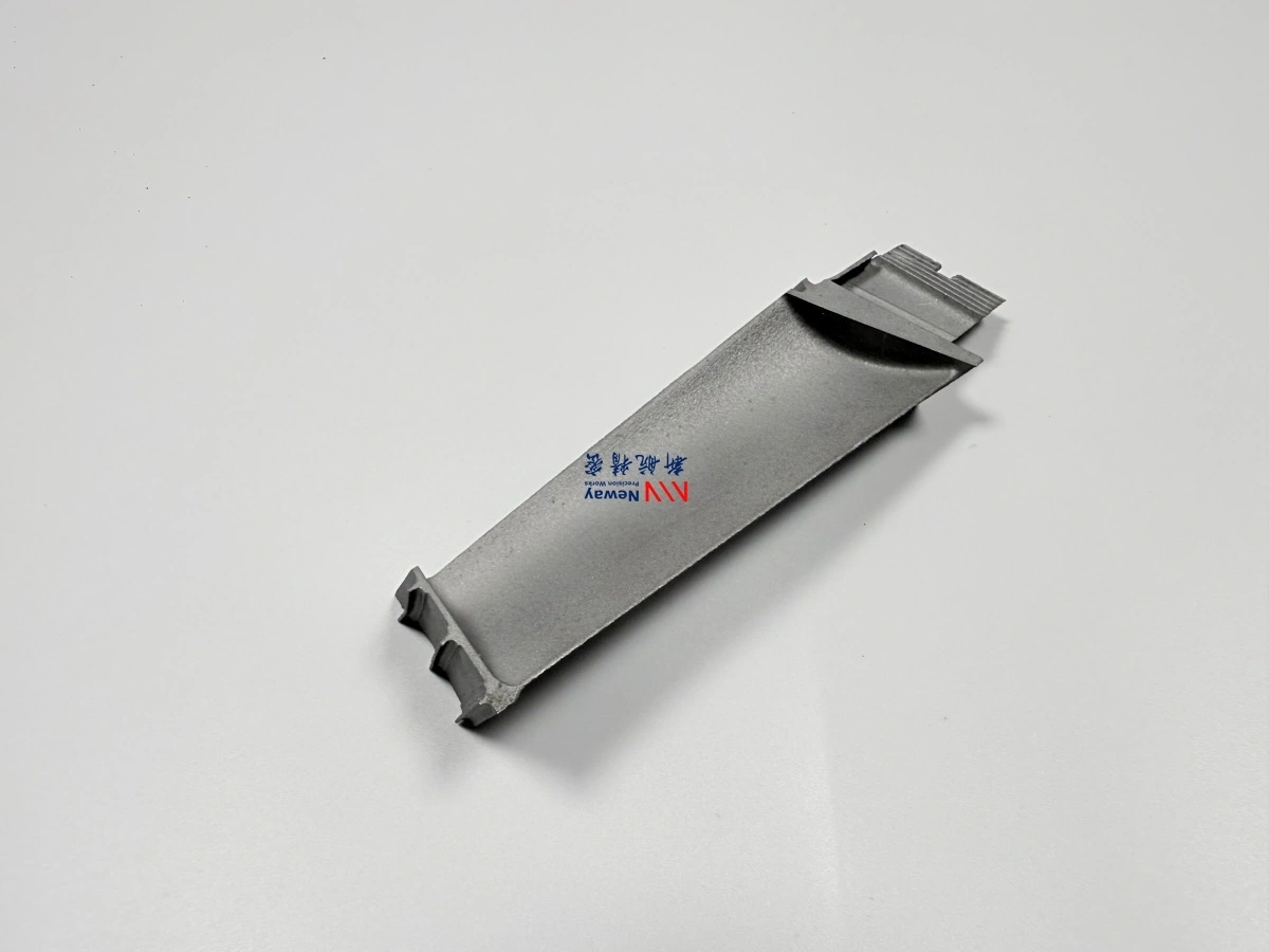
 The most commonly replaced combustion parts in GE 7F / 7FA gas turbines are transition pieces, combustion liners, fuel nozzles, crossfire tubes, igniters, flame detectors, seals, and related combustor support hardware. In practice, transition pieces, liners, and fuel nozzles usually account for the largest replacement value because they operate in the hottest combustion zone, where repeated starts, shutdowns, load swings, oxidation, and thermal fatigue can rapidly reduce service life.
1. Most Common GE 7F / 7FA Combustion Replacement Parts
Part | Main Damage Mechanism | Typical Service Effect | Replacement Frequency Level |
|---|---|---|---|
Transition pieces | Thermal fatigue, oxidation, coating spallation | Cracking, wall thinning, distortion, leakage risk | Very high |
Combustion liners | Direct flame exposure, hot spots, cyclic stress | Burn-through, local deformation, cooling-hole damage | Very high |
Fuel nozzles | Deposit buildup, flow erosion, thermal wear | Poor atomization, flow imbalance, combustion instability | Very high |
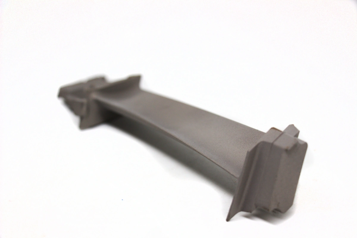
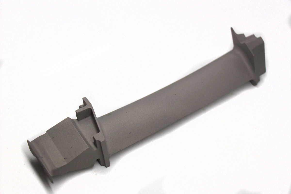
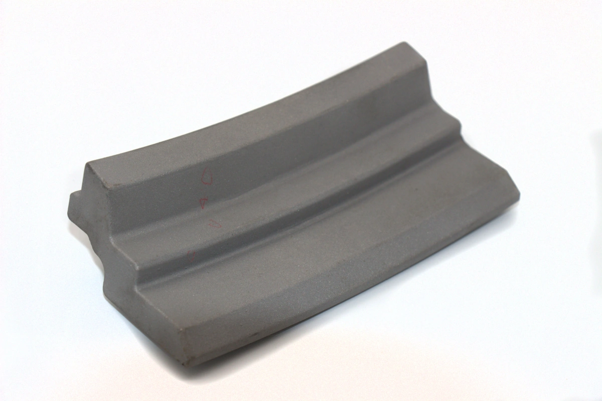
Crossfire tubes | Oxidation, cyclic cracking | Flame transfer issues, leakage, fit loss | High |
Igniters | Electrode wear, thermal shock | Weak ignition energy, difficult startup | High |
Flame detectors | Sensor aging, contamination | False alarms or unstable flame monitoring | Medium |
Seals and gaskets | Thermal relaxation, oxidation, handling wear | Air leakage, pressure loss, reduced efficiency | High |
Caps, collars, retainers, support hardware | Mechanical wear, heat damage | Loss of fit-up, secondary cracking, support instability | Medium to high |
2. Which Parts Usually Drive Most Outage Spending?
In most combustion overhauls, three part groups dominate the budget and urgency:
Priority | Part Group | Why It Matters |
|---|---|---|
1 | Transition pieces | These handle the combustor discharge path and directly influence downstream temperature distribution into the first turbine stage. |
2 | Combustion liners | These see direct flame exposure and often accumulate crack networks, oxidation damage, and local hot-spot distortion. |
3 | Fuel nozzles | Even small internal wear or deposits can shift fuel flow enough to affect emissions, flame shape, and hardware life. |
For many operators, these three categories can represent well over half of the combustion replacement value in a major outage, especially when the hardware includes repaired or fully new hot-gas-path grade alloy components.
3. Why These Parts Are Replaced So Often
Transition pieces are exposed to gas temperatures that can exceed 1,200°C class conditions locally, depending on operating mode, load pattern, and cooling effectiveness. Under these conditions, even small coating loss or wall thinning can accelerate cracking. Manufacturing routes for such hot-section parts often involve vacuum investment casting, precision forming, welding, and finish machining.
Combustion liners undergo repeated thermal gradients between startup, base load, shutdown, and cycling duty. In peaking or flexible-duty service, the accumulated thermal fatigue rate can be substantially higher than in stable baseload operation. Their repair and replacement decisions often depend on crack density, oxidation depth, cooling-hole condition, and dimensional stability after inspection.
Fuel nozzles are high-value precision flow components. A small change in passage geometry, tip wear, or blockage can alter spray quality and fuel split. In practical maintenance terms, a nozzle set that drifts out of balance can increase combustion dynamics, emissions deviation, and downstream hot streak risk. Related alloy part finishing often depends on superalloy CNC machining for critical features and tolerances.
4. Common Damage Patterns by Part Type
Part | Common Damage Pattern | Operational Impact |
|---|---|---|
Transition pieces | Axial cracks, corner cracking, oxidation thinning, distortion | Temperature maldistribution and reduced life of downstream turbine hardware |
Liners | Burn zones, louver cracking, hot-side fatigue, cooling feature damage | Combustion instability and local overheating |
Fuel nozzles | Coking, erosion, tip wear, internal flow-path contamination | Poor fuel distribution, unstable flame, higher maintenance risk |
Crossfire tubes | End cracking, oxidation, fit degradation | Reduced flame transfer reliability during startup |
Igniters | Electrode erosion, insulation failure | Longer light-off time or failed ignition attempt |
Seals | Flattening, oxidation embrittlement, installation damage | Leakage and combustor efficiency loss |
5. Material and Process Requirements for Replacement Parts
GE 7F / 7FA combustion replacements typically require nickel-based high-temperature alloys capable of handling oxidation, creep, and cyclic thermal stress. Depending on the part category, production may combine high-temperature alloy casting, precision weld restoration, controlled heat treatment, and protective thermal barrier coating.
For repaired or newly manufactured parts, verification normally includes dimensional inspection, structural evaluation, and metallurgical review. In demanding utility applications, replacement decisions are often based on crack length, wall-loss percentage, coating condition, and service hour history rather than visual appearance alone. That is why many buyers also require formal material testing before accepting hot-section hardware.
6. Summary
If you are sourcing... | Most likely replacement candidates |
|---|---|
Main combustion hot hardware | Transition pieces and liners |
Precision fuel delivery components | Fuel nozzles |
Startup and flame-transfer items | Crossfire tubes and igniters |
Leakage and support components | Seals, collars, retainers, combustor hardware |
In summary, the combustion parts most commonly replaced in GE 7F / 7FA gas turbines are transition pieces, combustion liners, and fuel nozzles, followed by crossfire tubes, igniters, seals, and related support hardware. These parts are replaced most often because they carry the highest thermal load and the greatest reliability risk in the combustion section. For related application and manufacturing references, see power generation, gas turbine components, and high-temperature alloy assemblies.