Stainless Manifold Microstructure: Printed vs Cast
Stainless manifold microstructure is where the three routes stop looking alike. A printed wall and a cast wall can measure the same 2.5 mm and still machine differently, because the grain, the skin and the residual stress field around that wall were produced in three different ways.
What does microstructure mean for a manifold?
Microstructure is the part of the specification that decides how the metal behaves under the cutter. For this manifold it shows up as four consequences: how much stock has to be removed before clean metal appears, how the wall moves when that stock comes off, how the flange holds flatness after machining, and what the surface finish ends up at.
The first consequence is measurable straight away. A casting arrives with a skin that has to be cut before the surface is steel, and a printed part arrives with a support scar and a different surface texture. The casting skin is a ceramic interface plus oxidation, about 0.3 mm deep here. Both need machining, but they need different depths, which is why the allowance on a casting is 1.5 mm and on a printed part 1.0 mm.
The second consequence is less visible and more expensive. Removing metal releases residual stress, and the stress field in a casting comes from shrinkage and cooling, while the field in a printed part comes from thermal cycling around a melt pool. The same cut therefore moves the two parts in different directions.
Everything after that follows the drawing rather than the route. The wall stays 2.5 mm, the flange closes to 0.05 mm flatness, the bolt holes gauge at M10×1.5 and the part is accepted to CT6 under ISO 8062-3. What changes with the route is the path to those numbers, not the numbers.
How does printed stainless differ from cast?
Printed stainless builds a part from a melt pool that moves, so the grain grows along the build direction and the part is effectively a stack of thin solidified layers. Cast stainless fills a cavity and solidifies from the mould wall inward, so the grain grows across the section and the last metal to freeze sits in the middle.
That difference is not cosmetic. A printed section has a fine, directional grain and a surface that carries partially melted powder; a cast section has a coarser, more equiaxed grain and a surface that carries ceramic and oxidation. The superalloy 3D printing route also leaves less machining stock on the outside, because the as-built surface is closer to the drawing than a shell surface is.
The practical comparison for this manifold is a table of numbers rather than a materials argument. Printed: allowance 1.0 mm, stress relief at 800 °C for 1.5 h, support removal before machining. Cast: allowance 1.5 mm, stress relief at 880 °C for 3 h, shell and skin removal before machining.
The casting route carries one extra variable. A vacuum investment casting part inherits the shell face, and the precision wax pattern surface matters twice: for the shape and for the skin to cut.
Where does residual stress land in each route?
Residual stress lands where the last metal to cool sits. In a casting, that is the interior of the section and the region under the shell skin, so the stress gradient points inward from the surface. In a printed part, each layer cools against the previous one, so the stress runs along the build direction and concentrates at the base and at any change of section.
The flange is where this matters most, because a flange is thin and flat and easy to move. A casting that is cut on one face releases stress and bows toward the cut; a printed part tends to lift at the edges, because the stress it releases was built in vertically rather than radially.
Both are handled by the same rule, which is to relieve before finishing rather than after. The casting is relieved at 880 °C for 3 h after cleaning, and the printed part at 800 °C for 1.5 h after support removal, and only then does either part go to a finishing cut.
That sequencing is the cheapest control available. A part that is finished before relief moves afterwards, and no amount of inspection catches a movement that happens after the inspector leaves.
A part that rests for 24 h before the finish cut moves less than one cut the same day, which is why the rest period sits in the process sheet rather than in a note.
Which cutting conditions hold 0.05 mm flatness?
The cutting conditions that hold 0.05 mm on this flange are a low clamping pressure, a three-setup sequence and a finishing pass that removes little enough to avoid re-loading the part. Clamping pressure stays below 1.0 MPa because a 2.5 mm flange deflects under a hard clamp and springs back when the vice opens.
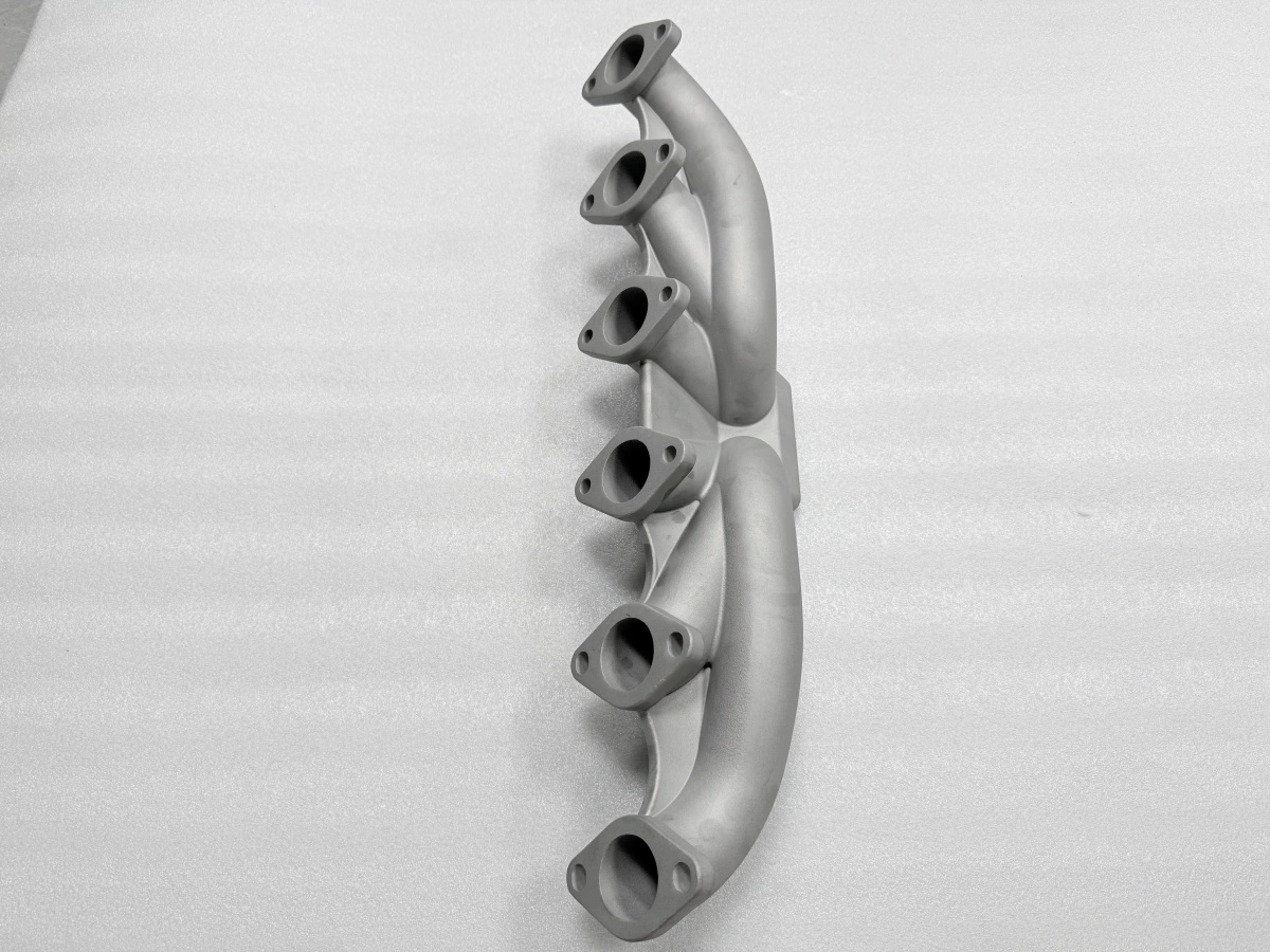
The three setups are the same for both routes. The first holds the turbo flange and faces three runners, the second turns the part and faces the other three, and the third finishes the turbo flange and the sealing faces in one position so that the two faces stay parallel to each other.
Toolpath matters as much as clamping. The superalloy CNC machining sequence runs roughing at 0.8 mm radial step, semi-finish and finish at 0.3 mm, and the finishing pass is where the 0.05 mm is actually made. A part that is roughed and finished in one pass will not hold it, whatever the machine.
The precision pouring parameters set the skin that removal must clear, so they are quoted with the allowance. Surface finish is checked on the same part. Blasting leaves the outer surfaces at about Ra 5 µm, and the sealing faces are held to Ra 1.6 µm because a gasket needs a defined texture rather than a polished one. That pair of numbers belongs to the drawing, not to the route.
How does heat treatment respond in each route?
Heat treatment responds differently because the two starting states have different stress histories. A casting relieved at 880 °C for 3 h is being taken through a cycle that dissolves and reprecipitates phases as well as relaxing stress, so the response is a combination of stress relief and structural change.
A printed part relieved at 800 °C for 1.5 h is being taken through a shorter, cooler cycle aimed at the stress that the build left behind. The shorter cycle is deliberate: the printed part has less section-level segregation to homogenise and more risk of grain growth if it is over-soaked.
What does not change is the requirement after treatment. Both parts are measured after 24 h of rest, both are checked at CT6 under ISO 8062-3 and both are scanned against the model with an acceptance band of ±0.9 mm. The stress relief in castings note applies to the casting cycle; the printed cycle is its own recipe with its own numbers.
The one thing to resist is copying one cycle onto the other. A casting run at 800 °C for 1.5 h will not be fully relieved, and a printed part run at 880 °C for 3 h risks a grain that no longer matches the data it was qualified on.
When does printed stainless stop paying off?
Printed stainless stops paying off when the volume passes the point where a tool would amortise, and for this manifold that point sits at 300 parts. Below it, the printed route carries the batch and the tool does not pay; above it, the tool spreads over enough parts that the unit price falls below the printed route.
The second limit is dimensional rather than commercial. A printed part can hold the drawing, but its surface and its stress field are not the casting's, so data collected on printed parts does not qualify a casting process. That is the same boundary the design freeze note draws for route selection, and the stainless casting case shows the same split in practice.
The third limit is scope. This comparison covers grain, skin and stress as they affect machining and heat treatment; it does not cover material property testing, hot isostatic pressing or weld repair, and it makes no claim about a specific alloy grade, which is set by the customer drawing.
Inside those limits the comparison is a working tool. It tells a machinist what to expect before the first cut, and it tells a planner which route's data can be carried into the series. Outside them, the honest answer is a test on the actual route rather than an argument from analogy.
Send the drawing, the route and the batch size, and the reply states which starting state the part will have, which relief cycle applies and what the machining sequence expects to remove.
FAQs