Industrial CT Inspection for Ceramic Core Turbine Vane Castings
A ceramic core turbine vane casting RFQ should define what CT inspection must prove. Buyers may need to see core shift, wall thickness, internal passage openness, residual ceramic, shrinkage, inclusion risk, or local mismatch between internal and external geometry. CT can be powerful, but it becomes expensive and unclear when the RFQ does not name the features, zones, acceptance method, and report output.
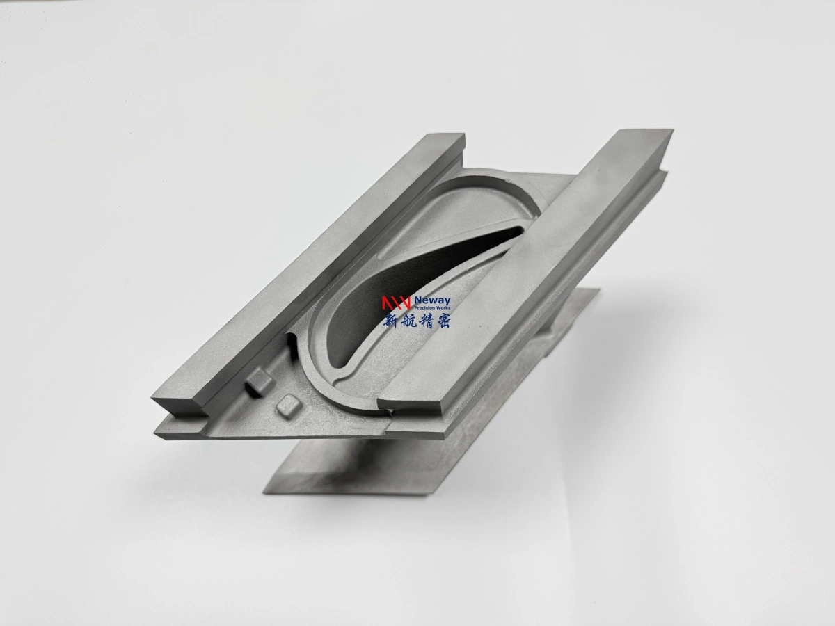
NewayAeroTech can support material testing and analysis for vane castings when buyers provide the drawing, model, casting route, ceramic core notes, inspection zones, delivery condition, and acceptance requirements. For a nozzle guide vane or static vane segment, the CT plan should connect the internal cooling geometry to the cast airfoil, platform, seal face, and machining scope.
Decide What CT Must Prove Before Scanning
For this RFQ, buyers should first define whether CT is being used for first-article validation, recurring lot inspection, defect investigation, or process development. A first article may need broader CT review to confirm ceramic core position and internal-passage geometry. A repeat lot may only need selected zones if the buyer has already approved the casting route. A defect investigation may focus on one suspect region rather than the full vane.
The buyer should provide a CAD model or drawing that identifies internal passages, wall-thickness targets, measurement zones, and surfaces that will be machined after casting. If the internal geometry is proprietary or not fully released, the buyer can still provide controlled sections or inspection zones. The supplier needs enough information to align CT measurements with the acceptance question.
CT resolution, scan envelope, and report detail depend on part size and feature size. A vane segment with thin walls and small cooling passages requires different scan planning than a solid platform boss. The RFQ should state the smallest feature that must be reviewed, the area of interest, and whether the buyer expects dimensional values, visual slices, a deviation map, or only pass/fail comments.
CT purpose | Feature focus | Buyer data needed |
|---|---|---|
First-article validation | Core position, wall thickness, and passage shape. | CAD model, target sections, and acceptance zones. |
Lot release | Recurring high-risk regions after process approval. | Sampling plan and report features. |
Defect investigation | Suspect shrinkage, inclusion, or blocked passage areas. | Problem description and location map. |
Process correction | Core movement, shell influence, and tooling feedback. | Part history, casting trial notes, and comparison parts. |
A CT request that only says scan the vane may produce images but not useful release evidence. Buyers should define the decision that will be made from the scan before the inspection is quoted.
Map Ceramic Core Shift and Wall Thickness Risk
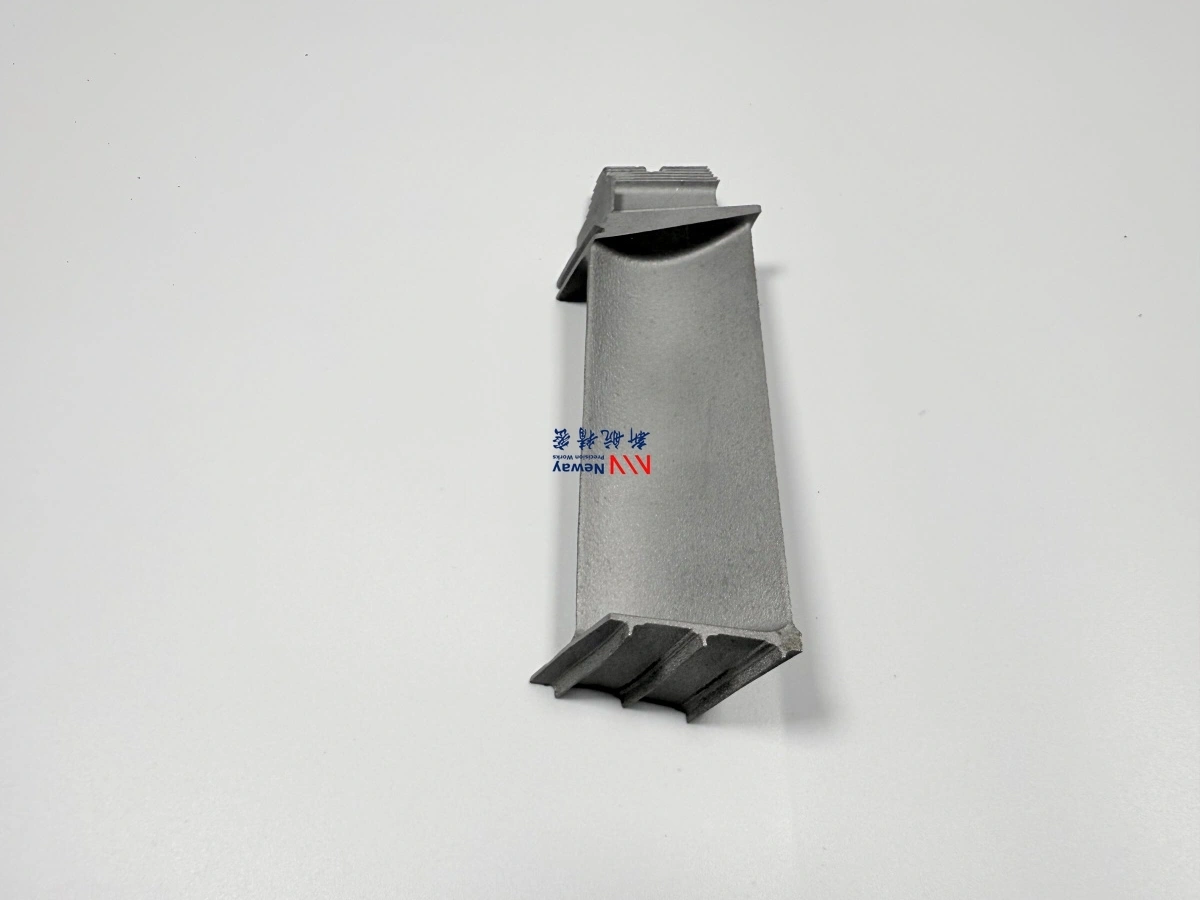
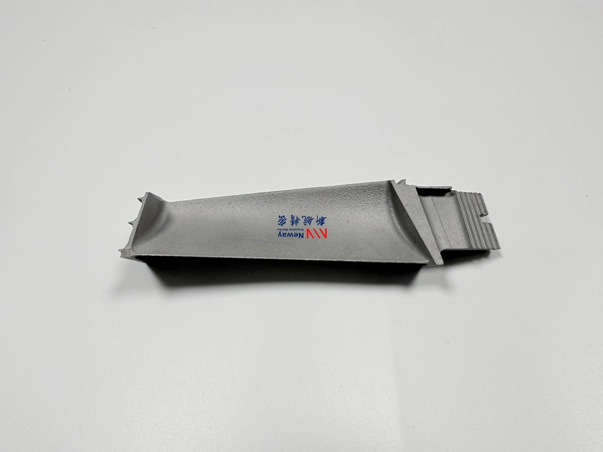
Ceramic core position controls the internal passages that make many turbine vanes manufacturable. If the core shifts, the vane can show local thin wall, uneven cooling passage shape, blocked sections, or mismatch between the internal channel and the external airfoil. CT is valuable because it can review internal geometry without cutting the part apart.
The RFQ should identify wall-thickness sections by airfoil height, chord position, platform transition, leading edge, trailing edge, and any high-risk turns in the passage. A single minimum wall value is rarely enough. The supplier needs to know where the value applies and whether the buyer wants measured thickness at points, section maps, or a color deviation comparison against nominal geometry.
Core shift should also be interpreted with manufacturing context. A small movement in a noncritical internal pocket may be acceptable, while a similar movement near a thin leading-edge passage may block release. The buyer should mark critical zones and noncritical zones so the CT report does not treat every deviation as equally important.
If the vane will be machined after casting, CT data should be tied to machining allowance. A platform face or seal surface may remove stock and change final local wall condition. The RFQ should state whether CT occurs before machining, after machining, or at both stages for the first article. That choice affects how core position is interpreted.
Internal feature | CT question | Report output to request |
|---|---|---|
Leading-edge passage | Is the passage open and aligned with the design intent? | Section images and measured wall zones. |
Trailing-edge passage | Is there blockage, thin wall, or local mismatch? | Slice review with marked suspect areas. |
Platform transition | Does core shift create shrinkage or wall-thickness risk? | CT sections tied to platform location. |
Machined seal face | Will later machining affect remaining wall or passage margin? | Comparison before and after machining if required. |
Separate CT, X-Ray, FPI, and CMM Responsibilities
CT should not be asked to replace every inspection method. X-ray can review internal casting indications, FPI can review surface indications after cleanup or machining, and CMM can verify external geometry, datums, and machined interfaces. CT is strongest when the buyer needs three-dimensional internal-passage or wall-thickness evidence. A practical RFQ assigns each method to the condition it can actually prove.
For a turbine vane casting, CT may be used on selected first articles to confirm ceramic core result, while X-ray may remain the regular internal defect review method for defined zones. FPI may occur after gate removal and machining. CMM may confirm platform, seal faces, mounting features, and airfoil sections. Combining methods is useful when each method has a defined responsibility.
The buyer should also define sequence. CT before machining can prove core position and gross internal geometry; CT after machining can reveal whether final stock removal affects local walls. FPI after machining can expose surface indications that were not visible earlier. CMM after machining proves external acceptance. The RFQ should name the sequence so the supplier can quote the correct handling and reporting effort.
Inspection sequence can create hold points. If CT must be accepted before machining begins, say so. If machining can continue while CT records are reviewed, say that as well. The supplier cannot schedule the vane intelligently unless the evidence that blocks the next operation is clear.
Method | Strong use | RFQ warning |
|---|---|---|
CT | Internal passage shape, core shift, wall thickness, blocked passages. | Define resolution need and zones; full-part CT may not be necessary. |
X-ray | Internal casting indications in selected zones. | Do not ask it to measure complex passage geometry by default. |
FPI | Surface indications after cleanup, machining, or blending. | Define inspected surfaces and acceptance reference. |
CMM | External datums, platform, seal faces, and machined features. | Provide datum scheme and feature list. |
Define CT Report Format for Buyer Review
A CT report can include raw images, selected slices, wall-thickness maps, dimensional data, deviation overlays, defect notes, and screenshots of suspect zones. The RFQ should state what the buyer actually needs for internal review. A purchasing team may only need pass/fail evidence, while an engineering team may need section views at named stations.
Report format should match the acceptance standard. If wall thickness is the main concern, request measured sections and minimum values at defined locations. If passage openness is the concern, request slice views through the passage and marked blockage locations. If core shift is the concern, request comparison against nominal passage centerline or wall-thickness distribution.
Data ownership and file format should be discussed before scanning. Some buyers want PDF reports only; others need 3D data, image stacks, or screenshots for design review. Large CT datasets can be difficult to transfer and may require controlled handling. The RFQ should name the expected deliverable so the supplier can price scan processing and reporting time accurately.
For first-article vane castings, report comments should be tied to manufacturing decisions. If CT shows core shift near the platform, the supplier may need to adjust wax assembly, core support, shell process, or heat-treatment handling. If CT shows acceptable internal geometry, the buyer can decide whether future lots need full CT, selected CT, X-ray, or sampling-based review.
First-Article CT Validation for Vane Casting Release
First-article CT validation should answer whether the casting route can repeatedly produce the internal geometry required by the vane design. The buyer should not only review one clean scan image. It should compare the scan to functional zones: leading-edge passage, trailing-edge passage, platform transition, machined surfaces, and any cooling features that affect downstream finishing.
The first-article package may include CT report, X-ray or FPI references, CMM data for external interfaces, material record, and notes about any casting-route correction. If the part is produced by vacuum investment casting, the package should connect core design, casting cleanup, machining allowance, and inspection results instead of treating CT as an isolated test.
Repeat-lot inspection should be agreed after first-article review. Some buyers may keep CT for every part when passages are critical. Others may use CT for first articles and high-risk samples, with X-ray, FPI, and CMM supporting regular release. The RFQ should define the intended repeat approach or ask the supplier to propose one after first-article evidence is reviewed.
Send NewayAeroTech the vane drawing, CAD model, internal passage information, wall-thickness zones, inspection standard, delivery condition, machining stage, and report format. A complete CT RFQ lets the supplier quote inspection evidence that supports casting release instead of simply producing scan images.
Related FAQs
How do NDT methods like CT scanning help detect freckle defects?
What is the role of X-ray testing in detecting inclusions in metal parts?
What are the most common defects in superalloy castings and how are they detected?
What are the main challenges in achieving defect-free single crystal guide vanes?
What testing methods ensure the quality of single crystal guide blades?