
Thin Wall Exhaust Manifold Casting: 0.4 mm Short, Then Fixed
The first article of this thin wall exhaust manifold casting came out 0.4 mm small on the six flange centers, and the second runner filled short at the tip. The fix took four changes: 2.2% shrinkage compensation instead of 2.0%, a 0.2 mm local cavity correction on two faces, one added in-gate at the short runner, and a re-cut parting face. The second run held ±0.15 mm across the batch, and the part has run since with a 0.1 mm drift measured after 300 pieces (case file).
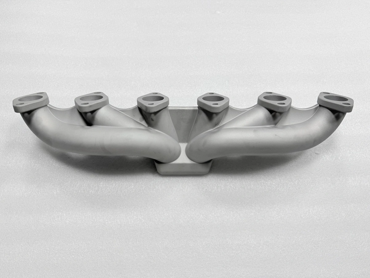
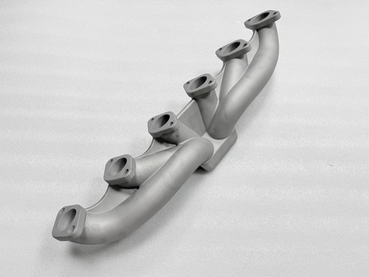
The part: six runners, one turbo flange, a 2.5 mm wall
The manifold is a stainless turbo exhaust part with six runners merging into one outlet flange and a 2.5 mm nominal wall. The wall is the constraint that drives everything else: it freezes in seconds, so the runner sections stop shrinking while the flange is still liquid and still drawing metal.
The tool is a four-cavity wax injection tool with three parting faces and eight ejector points, running at 75 °C wax temperature, 0.3 MPa injection pressure, 8 s hold and 60 s cooling. Patterns are assembled eight per tree, shelled in seven ceramic layers at about 8 mm each with 8 h of drying between layers, dewaxed at 165 °C and 7 bar, and poured at 1600 °C under −0.05 MPa with a 12 s fill.
None of those numbers is unusual for a manifold. What made this part a case was the combination: a wall thin enough that the runner freezes early, and a flange thick enough that it keeps feeding, so the two ends of the same casting disagree about how much they shrank.
First article: 0.4 mm small and a short fill
The first article was measured on the wax pattern at the six flange centers and the body length, then on the casting after shell and pour. The pattern read 0.4 mm small on the flange centers against a CAD model carrying the 2.0% scale, and the casting repeated the same direction. A 0.4 mm error is roughly a quarter of the 1.5 mm machining stock on those faces, which is recoverable once but not across a batch.
The second finding was not dimensional. The second runner filled short at the tip, about 6 mm from the end of the runner bore. A short fill at the far runner on a tree is usually a fill-time or a gating problem rather than a metal temperature problem, and the pattern evidence supported that: the pattern was complete, the shell was clean, and the short appeared only on that one runner position.
Two defects, two different levers. The dimensional error belonged to the cavity scale; the short fill belonged to the gating. Treating both with the compensation figure would have made one worse while fixing the other, which is the trap this case is written about.
Four corrections before the second pour
The compensation went from 2.0% to 2.2% on the cavity model, applied as a uniform scale before the tool paths were regenerated. That moved the flange centers by 0.4 mm in the right direction and left the body length within 0.1 mm.
The local correction came next: two flange faces were re-cut by 0.2 mm to take out the residual bias that a uniform scale cannot address on a part whose sections freeze at different times. The parting face was then refitted and checked to a 0.05 mm gap at each corner.
The fourth change was the in-gate. One gate was added at the short runner, sized so that the fill time at that end dropped without raising turbulence elsewhere on the tree. The pour itself stayed at 1600 °C and −0.05 MPa, and the fill time stayed at 12 s; only the entry changed.
Control point | First run | After correction |
|---|---|---|
Shrinkage compensation | 2.0% | 2.2% |
Local cavity correction | none | 0.2 mm on two faces |
Gating at runner 2 | one gate | two gates |
Parting gap | 0.10 mm | 0.05 mm |
Flange centers | 0.4 mm small | within ±0.15 mm |
Runner 2 fill | short, 6 mm | complete |
The table is the whole correction in one view: two numbers moved the geometry, two moved the process. The automatic wax press kept the press parameters constant across both runs, so the difference between the runs can be attributed to the tool and the gate rather than to operator settings.
Machining: three setups and the 0.08 mm detour
Machining runs in three setups on one datum chain: head flange and two runner faces, then the remaining four runner faces, then the bolt pattern. Flatness is specified at 0.05 mm per sealing face. On the first batch after the fix, one part measured 0.08 mm on a runner face after setup two.
That reading was traced to the order, not to the casting. The part had been clamped on a face that was machined in setup one, and the clamp load pushed the thin flange before the cut. Re-clamping on the boss pads and taking a lighter first pass brought the face back to 0.05 mm, and the remaining parts in the batch held it.
The bolt pattern is 4×M10×1.5, checked with a go/no-go gauge on the third setup. The detour is worth recording because it is the kind of error that looks like a casting problem: a 0.08 mm flatness reading on a part whose casting is inside CT6 under ISO 8062-3 is a fixturing effect, and chasing it in the cavity would have moved the whole tool for nothing.
What the exhaust manifold inspection record covers
The inspection record for this part covers three layers. The dimensional layer is a 3D scan at baseline and at final, compared against a ±0.9 mm acceptance band that sits inside the CT6 allowance of the drawing. The surface layer is X-ray and fluorescent penetrant inspection on the hot gas path, described in X-ray, FPI and CMM inspection. The material layer is a chemistry and mechanical test certificate from the material testing and analysis line.
What the record does not cover is worth stating as plainly. It does not contain a fatigue life result, a pressure test result or a customer acceptance signature. A dimensional report and a CT6 tolerance say the part is where it should be, not that it will survive a duty cycle; that judgement belongs to the customer's own validation.
The record is also what makes the next batch cheaper. With the baseline scan and the first-article measurements on file, the correction history is traceable, and the drift that showed up at 300 pieces, 0.1 mm, was read as a trend against that baseline rather than as a new problem. That reading is the same one described in dimensional control.
The lesson from this case is not the 2.2%. It is that two defects that look alike on a report, a size error and a short fill, needed two different corrections, and that the dimensional one belonged in the cavity while the filling one belonged in the gate. Send a first-article report in this format and we will tell you which lever each deviation belongs to, priced with the vacuum investment casting route. Comparable programs are on stainless steel casting production and gas turbine lost wax casting, and the gating side is covered in precision pouring. The machining sequence is run by the CNC machining team, and the reasoning behind the three setups is in CNC machining on castings.
FAQs
How Much Machining Allowance Do Exhaust Manifold Flanges Need?
Exhaust Manifold Wax Pattern: What Does a First Article Prove?