Монокристаллическое литье турбинного ротора из сплава IN713LC
Введение
Турбинные роторы являются центральным элементом, определяющим производительность и долговечность газовых турбин, работающих в условиях экстремальных центробежных, тепловых и механических нагрузок. Традиционные методы литья часто приводят к образованию границ зерен, которые ограничивают усталостные характеристики и сопротивление ползучести. Чтобы преодолеть это, монокристаллическое литье предлагает превосходное решение — устраняя границы зерен и выравнивая ориентацию зерна вдоль оптимальной оси [001].
В Neway AeroTech мы специализируемся на монокристаллическом литье критически важных вращающихся компонентов с использованием IN713LC — высокопроизводительного никелевого суперсплава с отличными высокотемпературными механическими свойствами. Наши роторы изготавливаются с использованием передовых технологий вакуумного литья по выплавляемым моделям и направленной кристаллизации, отвечая требованиям аэрокосмической отрасли, энергетики и оборонных применений.
Основная технология монокристаллического литья турбинных роторов из сплава IN713LC
Изготовление восковых моделей Изготавливаются крупноформатные восковые модели для точного воспроизведения геометрии турбинных роторов, включая ступицу, лопатки и балансировочные элементы.
Формирование керамической оболочки Высокопрочные керамические оболочки наносятся слоями (толщиной ~6–10 мм) с использованием суспензии и огнеупорной обсыпки для обеспечения термостойкости и структурной целостности.
Интеграция селектора зерна В форму включается винтовой селектор для обеспечения зарождения и роста одного кристалла вдоль ориентации [001].
Вакуумно-индукционная плавка Сплав IN713LC плавится при ~1450°C в вакуумных печах (≤10⁻³ Па), что минимизирует оксиды, газовую пористость и ликвацию.
Направленная кристаллизация Форма вытягивается из горячей зоны со скоростью 2–4 мм/мин, формируя полностью выровненную монокристаллическую структуру ротора без границ зерен.
Удаление оболочки и очистка После литья керамические формы удаляются с помощью гидроабразивной обработки под высоким давлением и химической очистки для сохранения точной геометрии.
Горячее изостатическое прессование (ГИП) ГИП проводится при 1150°C и 150 МПа для устранения внутренней пористости и повышения механической целостности.
Термообработка и старение Роторы проходят цикл растворяющей термообработки и старения для улучшения микроструктуры и оптимизации распределения γ'-фазы.
Свойства материала IN713LC для турбинных роторов
IN713LC выбран благодаря своим превосходным высокотемпературным характеристикам, фазовой стабильности и литейным свойствам:
Максимальная рабочая температура: 982°C (1800°F)
Предел прочности при растяжении: ≥1034 МПа
Сопротивление ползучести (разрушающее напряжение): ≥200 МПа после 1000 часов при 760°C
Ориентация зерна: Монокристалл [001], отклонение <2°
Стойкость к окислению: Отличная в условиях турбинного выхлопа
Доля гамма-прим фазы: >50% для поддержания несущей способности
Пример из практики: Монокристаллический ротор из сплава IN713LC для силовой турбины
Предпосылки проекта
Производитель силового оборудования поручил Neway AeroTech изготовить монокристаллические турбинные роторы из сплава IN713LC для высокоэффективной промышленной газовой турбины, работающей непрерывно при 950–980°C. Целью было достижение >20 000 часов работы с минимальной деформацией и высокой балансировкой вращения.
Области применения роторов
Роторы для энергетики (например, Siemens SGT, GE LM series): Используются в базовых газовых турбинах, требующих стойкости к ползучести и окислению.
Роторы сердцевины авиационных двигателей: Подвергаются высокоскоростному вращению, требуя стойкости к усталости и термическим ударам.
Турбины морского движения (например, LM2500+): Работают в коррозионных средах с непрерывными тепловыми циклами.
Роторы турбореактивных и турбовентиляторных двигателей для оборонной техники: Критически важны для готовности к выполнению задач при быстрых изменениях нагрузки и маневрах с высокими перегрузками.
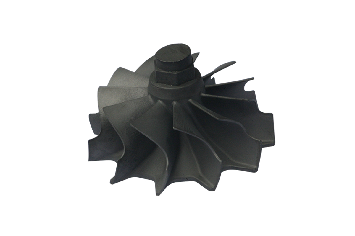
Конструктивные особенности ротора
Центральное отверстие и монтажный интерфейс для соединения с валом
Корневые части и бандажные полки лопаток, сформированные в монолитной конструкции
Балансировочные отверстия, охлаждающие каналы и концевые уплотнения
Сложные профили лопаток, выровненные по потоку
Технологический процесс изготовления монокристаллического ротора из сплава IN713LC
Комплексное проектирование формы и селектора Специальные восковые сборки для ротора включают селекторы зерна, литниковые системы и керамические холодильные плиты для оптимизированного управления вытягиванием.
Выполнение вакуумного литья Сплав IN713LC плавится и заливается в вакууме с использованием прецизионного оборудования для направленной кристаллизации.
ГИП обработка после литья ГИП при 1150°C/150 МПа гарантирует структуры без пористости и улучшенные усталостные характеристики.
Термообработка Растворяющая обработка и старение корректируют микроструктуру для фазовой стабильности и термостойкости.
Чистовая обработка на станках с ЧПУ Ключевые поверхности обрабатываются с использованием обработки суперсплавов на станках с ЧПУ для поддержания жестких допусков и вращательной симметрии.
Контроль и неразрушающий контроль Полный размерный контроль с помощью КИМ и проверка внутренних дефектов с помощью рентгеновского и ультразвукового методов.
Основные сложности при монокристаллическом литье роторов
Избежание посторонних зерен в зонах с несколькими лопатками и толстыми сечениями
Контроль скорости охлаждения для сложных геометрий
Поддержание ориентации [001] по всей длине лопаток переменной длины
Достижение балансировки и размерной стабильности после кристаллизации
Результаты и верификация
100% монокристаллическая структура с подтвержденной ориентацией [001]
Отклонение зерна <2°, подтверждено методом EBSD
Прочностные характеристики и сопротивление ползучести превысили расчетные показатели
Динамическая балансировка ротора поддерживалась в пределах ±3 г·см без корректировки
Все детали прошли неразрушающий контроль без критических дефектов
Часто задаваемые вопросы
Зачем использовать монокристаллическое литье для турбинных роторов?
Может ли IN713LC обеспечить достаточные характеристики для вращающихся деталей?
Какие испытания гарантируют целостность ротора после монокристаллического литья?
Как поддерживается динамическая балансировка в монокристаллических роторах?
В каких отраслях используются монокристаллические турбинные роторы из сплава IN713LC?
