سبائك عالية الحرارة إنكونيل 718 أجزاء أنابيب وقود محرك طيران مطبوعة ثلاثية الأبعاد
مقدمة في التصنيع التجميعي لإنكونيل 718 لمكونات أنابيب الوقود
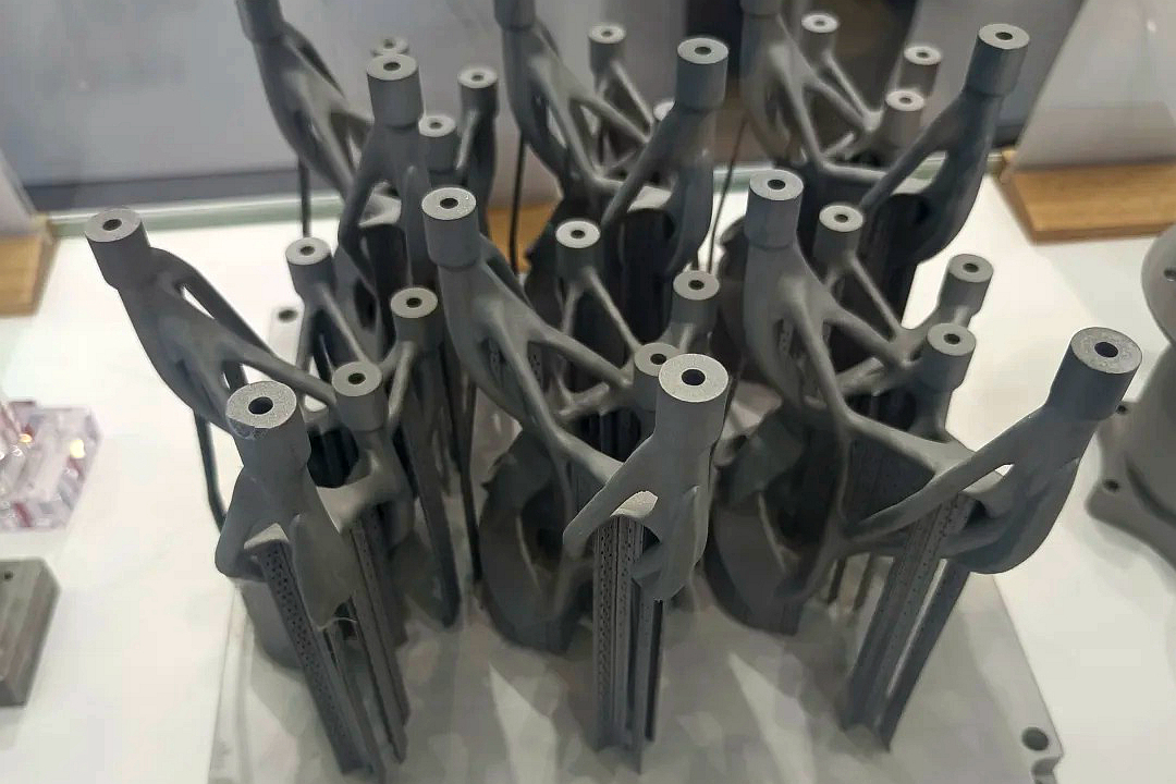
إنكونيل 718 هو سبيكة فائقة قائمة على النيكل مصممة لقوة فئة الطيران، ومقاومة التآكل، والأداء طويل الأمد في درجات الحرارة العالية. مع الطباعة ثلاثية الأبعاد، يتيح إنكونيل 718 تصنيع أنابيب وقود محركات طيران معقدة ذات هندسة محسنة، ووزن مخفض، ومقاومة ممتازة للإجهاد.
في Neway Aerotech، نتخصص في التصنيع التجميعي لإنكونيل 718 باستخدام صهر الليزر الانتقائي (SLM) لتقديم مكونات طيران دقيقة، بما في ذلك أنابيب وقود المحرك وأنظمة توجيه السوائل.
قدرات التصنيع التجميعي لأنابيب وقود الطيران
معلمات العملية
المعلمة | القيمة | الوصف |
|---|---|---|
طريقة الطباعة | صهر الليزر الانتقائي (SLM) | يتيح بناءً عالي الدقة وكثافة عالية |
سمك الطبقة | 30–50 ميكرومتر | يدعم ميزات الأنابيب ذات الجدران الرقيقة |
سمك الجدار | 0.8–1.5 ملم | مثالي لقنوات الطيران الحاملة للضغط |
خشونة السطح (كما بُني) | Ra 8–15 ميكرومتر | يمكن تقليلها من خلال التلميع أو معالجة التدفق الداخلي |
المعالجة اللاحقة | HIP، الشيخوخة، التشغيل الآلي CNC | يضمن السلامة الميكانيكية والدقة الأبعادية |
لماذا إنكونيل 718 لتطبيقات أنابيب الوقود
الخاصية | القيمة | الفائدة الوظيفية |
|---|---|---|
درجة حرارة التشغيل | حتى 980°م | يتعامل مع الأحمال الحرارية في بيئات التوربينات |
إجهاد الخضوع @ 700°م | ≥ 720 ميجا باسكال | يحافظ على الشكل تحت الإجهاد الدوري والضغط الداخلي |
مقاومة التآكل | ممتازة في الوسائط المؤكسدة | يقاوم التعرض للوقود وغازات الاحتراق |
عمر الإجهاد | >10⁸ دورة عند 650 ميجا باسكال | مناسب لمواقع تركيب التوربينات الاهتزازية |
قابلية اللحوم والمطيلية | عالية | يتيح حرية التصميم مع التركيبات المتكاملة |
استراتيجية المواد والمعالجة
المسحوق: إنكونيل 718 مُذرَّر بالغاز، كروي D50 ~35 ميكرومتر، معتمد للاستخدام في الطيران.
اتجاه البناء: محاذاة لتقليل الدعم في مناطق التدفق وتجنب تشوه القنوات الداخلية.
المعالجة اللاحقة:
HIP لإزالة المسامية الداخلية.
المعالجة الحرارية وفقًا لـ AMS 5663: محلول عند 980°م + شيخوخة عند 720°م/8 ساعات + 620°م/8 ساعات.
التشغيل الآلي CNC لواجهات الموصلات، الشفاه، وهندسة الخيوط.
التخميل لمتانة مقاومة التآكل.
دراسة حالة: أنبوب نقل وقود مطبوع ثلاثي الأبعاد من إنكونيل 718 لتوربينات الطيران
خلفية المشروع
طلب مجمع محركات توربينية أنبوب وقود مصمم خصيصًا بهندسة جدار رقيق، وأقواس متكاملة، وتوجيه غير خطي. تضمن التصنيع التقليدي ثنيًا متعدد القطع، ولحامًا، وربطًا، مما أدخل نقاط فشل محتملة وطال وقت التسليم.
سير عمل التصنيع
التصميم: نموذج ثلاثي الأبعاد معقد بجدار اسمي 1.2 ملم ومشابك/منافذ متكاملة.
الطباعة: SLM على نظام 400 واط، طبقات 40 ميكرومتر، جو من الأرجون.
المعالجة اللاحقة:
HIP عند 1200°م / 100 ميجا باسكال لمدة 4 ساعات.
معالجة حرارية وشيوخة.
تنعيم السطح الداخلي إلى Ra ≤ 5 ميكرومتر باستخدام تشغيل التدفق الكاشط.
التشطيب:
شفاه AN مشغلة آليًا بدقة ±0.01 ملم.
مقابس جاهزة للحхам تم طحنها وتشطيب حوافها.
CMM تحقق من محاذاة وتحملات التثبيت.
التحقق والفحص
أظهر فحص الأشعة السينية و الاختبار بالموجات فوق الصوتية سلامة ترابط بنسبة 100%.
اختبار التسرب عند ضعف ضغط التشغيل (7 بار) بدون أي فشل.
اختبار الدورة الحرارية 500 دورة بين 100°م و 950°م—لم يلاحظ أي تدهور أبعادي أو مجهري.
النتائج والتحقق
ألغى أنبوب وقود إنكونيل 718 المطبوع 5 وصلات ملحومة، وخفض الوزن بنسبة 18%,وقصر جدول التوريد بأكثر من 40%. تم اجتياز جميع متطلبات الاختبارات الميكانيكية والحرارية والتدفق للدمج في مجموعة توربين معتمدة.
الأسئلة الشائعة
ما هو الحد الأدنى لسمك الجدار الذي يمكن طباعته بموثوقية لأنابيب وقود إنكونيل؟
هل يمكن لحام أنابيب إنكونيل 718 المطبوعة لاحقًا أو تلحيمها بالنحاس بمكونات معدنية أخرى؟
أي تشطيب سطحي يحسن التدفق ويقلل من انخفاض الضغط في خطوط الوقود المطبوعة؟
هل تعتبر معالجة HIP والمعالجة الحرارية ضرورية لمكونات توجيه الوقود الحرجة للإجهاد؟
هل يمكن إجراء اختبارات الضغط والاهتزاز والدورة الحرارية قبل الشحن؟
