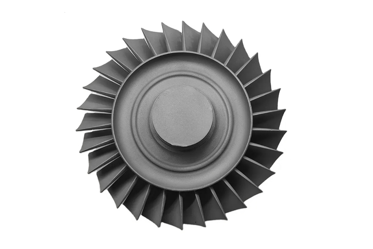
Turbine Shrouds and Seal Segments for Gas Turbine Hot Section Repair
NewayAeroTech manufactures custom turbine shrouds, seal segments, blade ring segments, hot gas path segments, shroud blocks, and wear-resistant sealing components for gas turbine hot section repair projects. These parts can be produced from customer drawings, used samples, 3D scan data, or turbine model information, then finished through casting, CNC machining, EDM, heat treatment, coating preparation, and inspection.
For power generation gas turbines, shrouds and seal segments are not simple protective blocks. They help control blade tip clearance, improve sealing efficiency, protect surrounding hot section structures, and maintain stable gas path performance. If the shroud contour, sealing face, segment fit, coating surface, or mounting interface is incorrect, turbine efficiency and hot section reliability can be affected.
NewayAeroTech supports power generation turbine hot section parts manufacturing for replacement shroud segments, seal blocks, blade ring segments, and custom gas turbine repair parts.
Direct Answer: Custom Turbine Shrouds and Seal Segments
NewayAeroTech provides custom turbine shrouds and seal segments for gas turbine hot section repair and replacement projects. Depending on the original part design, material requirement, coating system, and inspection standard, the manufacturing route may include special alloy casting, vacuum investment casting, CNC machining, EDM, heat treatment, post-processing, coating preparation, and final inspection.
Our manufacturing support can cover:
Custom turbine shrouds for gas turbine repair
Replacement seal segments for power generation turbines
Blade ring segments and hot gas path segment manufacturing
Shroud blocks and wear-resistant sealing components
Superalloy shroud segment casting and machining
Small-batch repair parts and long-term spare shroud supply
The goal is to provide finished hot section shroud and seal segment replacement parts with controlled arc geometry, sealing surfaces, mounting slots, segment fit, material consistency, coating-ready surfaces, and inspection documentation.
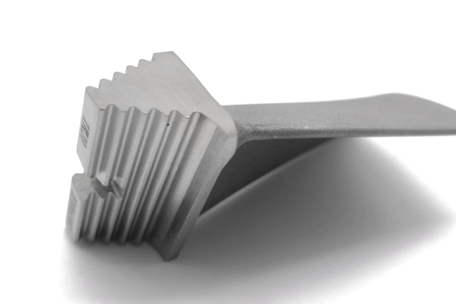
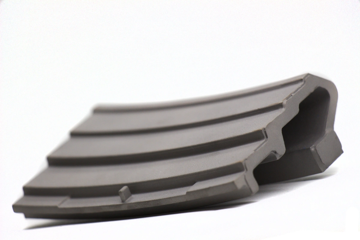
Component Function of Turbine Shrouds and Seal Segments
Turbine shrouds and seal segments are installed around rotating turbine blades in the hot gas path. Their main function is to control the clearance between the blade tip and surrounding stationary structure. This clearance affects gas leakage, turbine efficiency, blade tip rubbing risk, and hot section durability.
In gas turbine service, shrouds and seal segments perform several important functions:
Control blade tip clearance and reduce gas leakage
Improve turbine sealing efficiency and stage performance
Protect surrounding casing or support structures from hot gas exposure
Provide replaceable wear and thermal protection surfaces
Maintain segment-to-segment fit around the blade path
Support coating systems that resist oxidation, wear, and thermal fatigue
Because these parts are closely related to turbine efficiency and hot section reliability, replacement shrouds must be manufactured with careful control of arc profile, sealing face geometry, mounting features, and surface quality.
Why Shrouds and Seal Segments Need Replacement
Turbine shrouds and seal segments operate in a high-temperature environment with gas flow, blade tip interaction, vibration, oxidation, coating degradation, and thermal cycling. Over long service intervals, these conditions can damage the shroud surface and change the clearance between blade tips and the stationary sealing structure.
Common failure modes include:
Thermal cracks caused by repeated start-stop cycles
Oxidation or hot corrosion on gas-facing surfaces
Blade tip rubbing wear or local surface loss
Coating spalling, peeling, or erosion
Seal face damage or loss of controlled clearance
Segment distortion, bowing, or mismatch between adjacent pieces
Mounting slot wear, positioning hole damage, or interface deformation
Cracks or defects found during outage inspection
When wear, cracks, coating failure, or dimensional change exceed the repair limit, replacement shroud segments are needed to restore hot gas path sealing performance and turbine operating reliability.
Material Options for Hot Section Shrouds and Seal Segments
Turbine shrouds and seal segments require materials that can resist high temperature, oxidation, wear, thermal fatigue, and gas path erosion. Material selection depends on turbine model, stage location, temperature, blade tip interaction, coating system, and original specification.
Common material choices include Inconel alloys, Stellite alloys, cobalt-based alloys, Rene alloys, and other wear-resistant superalloys. For replacement parts, the material should follow the original drawing or verified sample data whenever possible.
NewayAeroTech supports Inconel alloy vacuum investment casting for nickel-based hot section shroud and seal parts. For wear-resistant and cobalt-based applications, Stellite alloy vacuum investment casting may be reviewed. For advanced turbine hot-section programs, Rene Alloys vacuum investment casting can support material comparison and replacement part development.
Material Family | Typical Use in Shroud Projects | Selection Consideration |
|---|---|---|
Inconel alloys | Nickel-based shrouds, seal segments, and hot gas path components | Useful for high-temperature strength, oxidation resistance, and cast superalloy performance |
Stellite alloys | Wear-resistant seal segments and hot section sealing surfaces | Suitable when wear resistance, hot corrosion resistance, and cobalt alloy durability are required |
Rene alloys | Advanced turbine hot-section shrouds and related components | May be reviewed when higher hot-section performance is required by the original design |
Wear-resistant superalloys | Blade tip sealing zones and replaceable hot gas path wear parts | Selected according to rubbing condition, coating system, oxidation exposure, and repair strategy |
Manufacturing Route for Turbine Shrouds and Seal Segments
Shrouds and seal segments usually require a combined manufacturing route because the parts include cast geometry, curved arc surfaces, mounting features, sealing faces, and coating-controlled regions. Casting creates the near-net-shape body, while CNC machining finishes the interfaces that control assembly and segment fit.
A typical route may include:
Review turbine model, stage location, drawings, old samples, or 3D scan data
Confirm alloy grade, casting route, coating requirement, and inspection standard
Produce casting tooling, wax patterns, ceramic shells, and process allowances
Cast the shroud or seal segment blank by special alloy casting or vacuum investment casting
Apply heat treatment or post-casting processing according to material requirements
Machine arc surfaces, sealing faces, mounting slots, positioning holes, and datum areas
Use EDM for slots, narrow features, sharp internal corners, or tool-access-limited areas when required
Prepare surfaces for coating, wear-resistant treatment, or customer-specified post-processing
Inspect arc profile, segment fit, sealing surfaces, casting soundness, and final dimensions
NewayAeroTech provides special alloy casting for turbine shrouds where high-temperature material behavior, geometry, and downstream machining requirements must be considered together. For near-net-shape superalloy blanks, vacuum investment casting for shroud segments can also support complex hot section replacement parts.
CNC Machining Focus for Seal Segments
CNC machining is critical for turbine shrouds and seal segments because these parts must fit accurately around the blade path and maintain controlled sealing surfaces. The cast blank provides the main material and shape, but machining defines final function.
NewayAeroTech provides superalloy CNC machining for seal segments, including nickel-based, cobalt-based, and wear-resistant superalloy materials.
Machining focus areas include:
Arc-shaped inner and outer contours
Sealing faces and blade tip clearance surfaces
Mounting grooves, slots, and retaining features
Positioning holes and assembly reference features
Segment-to-segment mating surfaces
Datum surfaces for CMM and arc inspection
Coating allowance surfaces and masking boundaries
Machining datum selection is important because segment geometry must match both the turbine casing and adjacent shroud segments. A local dimension may be correct, but the segment can still fail fit-up if arc geometry and mating surfaces are not coordinated.
EDM and Local Feature Processing for Shroud Segments
Some shroud segments include narrow slots, undercuts, sharp corners, cooling-related openings, or tool-access-limited geometry. These features may be difficult to machine by conventional cutting tools, especially when the material is a hard nickel-based or cobalt-based superalloy.
EDM can be used for local features where conventional machining creates too much cutting force or tool access is limited. For seal segments, EDM processing should control:
Slot width and boundary accuracy
Sharp internal corner geometry
Local hole or opening size
Recast layer and edge condition
Post-EDM cleaning before coating or final inspection
Compatibility with sealing surfaces and wear-resistant coating areas
If EDM features are located near sealing surfaces or coating boundaries, the process should be coordinated with final inspection and post-processing requirements.
Post-Process and Coating Preparation for Hot Section Shrouds
Hot section shrouds and seal segments may require heat treatment, stress relief, surface cleaning, coating preparation, polishing, or wear-resistant surface treatment before delivery. The correct post-process route depends on material grade, coating system, service temperature, and original design.
NewayAeroTech supports superalloy post-process and coating preparation to connect casting, machining, surface condition control, coating preparation, and final inspection into a complete manufacturing workflow.
Post-processing may include:
Heat treatment for material condition and microstructure control
Stress relief after machining or EDM where required
Surface cleaning and oxide removal
Coating preparation for oxidation-resistant, abradable, or thermal barrier coating systems
Deburring and edge finishing around slots, holes, and sealing faces
Final surface review before inspection and delivery
Coating allowance should be considered before final machining. If the coating thickness changes the sealing face, segment fit, or blade tip clearance surface, the part may pass pre-coating inspection but fail final assembly after coating.
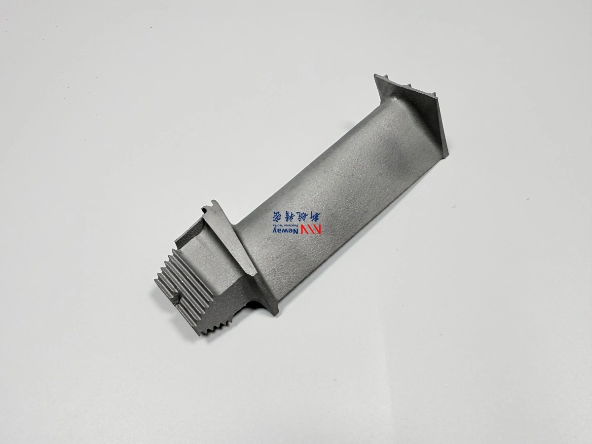
Critical Geometry of Turbine Shrouds and Seal Segments
Turbine shrouds and seal segments must maintain accurate arc geometry and segment-to-segment fit. These parts are usually assembled as multiple segments around the turbine blade path, so local errors can accumulate and affect the complete ring assembly.
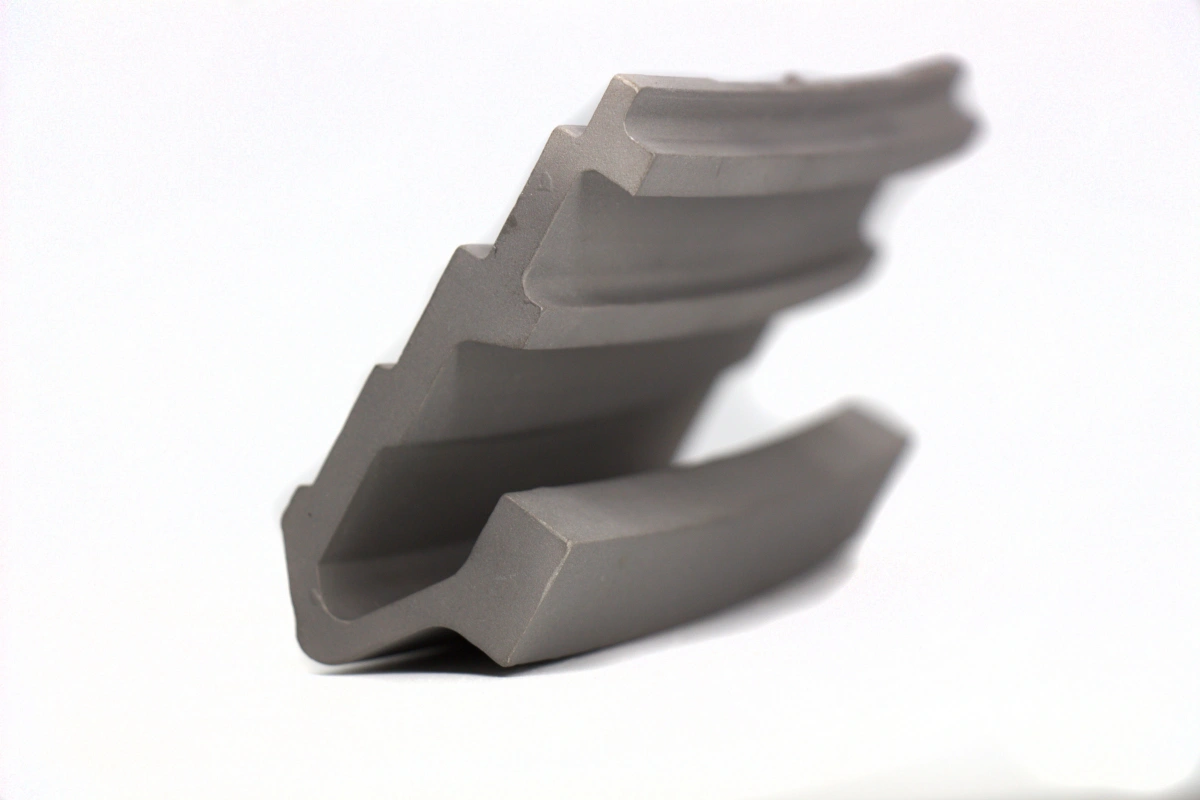
Critical geometry includes:
Inner arc contour and blade tip clearance surface
Outer arc contour and casing interface
Segment end faces and gap control between adjacent segments
Sealing faces and wear-resistant contact regions
Mounting slots, hooks, grooves, and retaining features
Positioning holes and datum surfaces
Coating boundaries and masked areas
If the arc geometry is incorrect, the assembled shroud ring may create uneven blade clearance. If sealing surfaces are damaged or inaccurate, hot gas leakage can increase. If segment interfaces are inconsistent, assembly stress and local wear may become worse during service.
Inspection for Turbine Shrouds and Seal Segments
Inspection is essential because turbine shrouds and seal segments must satisfy both casting quality and assembly geometry requirements. A complete inspection plan should verify material, casting soundness, arc profile, segment fit, sealing surface quality, and final dimensions.
Inspection Item | What to Check | Why It Matters |
|---|---|---|
Arc profile | Inner radius, outer radius, curvature, blade path geometry | Controls blade tip clearance and segment ring fit |
Segment fit | End faces, gap, mating surfaces, assembled segment continuity | Prevents leakage, assembly stress, and uneven wear |
Sealing surface dimensions | Flatness, profile, coating allowance, wear surface geometry | Supports sealing efficiency and controlled blade tip clearance |
FPI | Surface cracks and open defects | Identifies crack risk before coating, assembly, or delivery |
X-ray or CT | Internal porosity, shrinkage, inclusions, hidden casting defects | Verifies casting soundness for hot section service |
CMM inspection | Mounting slots, positioning holes, datum surfaces, mating geometry | Confirms dimensional accuracy and assembly reliability |
Inspection requirements should be confirmed before quotation because arc inspection, segment fit checks, FPI, X-ray, CT, CMM, and coating-related inspection can affect cost and lead time.
Reverse Engineering Support for Shroud and Seal Segment Replacement
Many gas turbine shroud and seal segment replacement projects begin with worn parts, incomplete drawings, or 3D scan data. Reverse engineering must identify original functional geometry instead of copying service damage.
NewayAeroTech can review replacement projects based on:
Original drawings and 3D CAD files
Used shroud or seal segment samples
3D scan data and reconstructed models
Photos showing cracks, oxidation, rubbing wear, coating loss, or sealing damage
Material analysis from old parts
Turbine model, stage number, and hot section operating condition
For worn seal segments, blade rubbing marks, coating loss, oxidized surfaces, distorted end faces, and damaged mounting slots should not be copied blindly. The replacement part should be reconstructed around functional arc geometry, sealing surfaces, and assembly fit.
Supplier Value for Hot Section Shroud Repair Projects
A qualified turbine shroud supplier should provide more than casting capacity. The supplier should understand blade tip clearance, sealing function, material selection, casting route, machining datum, coating allowance, segment fit, and inspection planning.
NewayAeroTech supports hot section shroud repair and replacement projects by providing:
High-temperature alloy and wear-resistant material review
Special alloy casting and vacuum investment casting options
CNC machining for arc contours, sealing faces, mounting slots, and datum features
EDM review for slots, holes, sharp corners, and tool-access-limited features
Heat treatment, surface cleaning, and coating preparation support
Arc profile, segment fit, FPI, X-ray, CMM, and final inspection planning
Prototype, small-batch repair parts, and long-term spare shroud manufacturing
This integrated route helps reduce communication gaps between casting, machining, coating, and inspection suppliers, especially when repair projects have tight power plant outage schedules.
RFQ Checklist for Turbine Shrouds and Seal Segments
To quote turbine shrouds and seal segments accurately, customers should provide technical data related to material, geometry, coating, inspection, and service condition. This helps the supplier evaluate casting feasibility, machining cost, inspection requirements, and delivery risk.
A complete RFQ should include:
Turbine model, stage number, part name, part number, and revision level
2D drawing and 3D CAD file if available
Used shroud sample, photos, or 3D scan data if reverse engineering is required
Required material grade, such as Inconel, Stellite, Rene alloy, cobalt alloy, or customer-specified superalloy
Casting route requirement, such as special alloy casting or vacuum investment casting
Heat treatment, coating, abradable surface, or post-processing requirements
Arc profile, sealing face, blade clearance surface, mounting slot, and segment fit requirements
Inspection requirements such as FPI, X-ray, CT, CMM, material report, arc inspection, or coating inspection
Quantity for prototype, repair batch, or long-term spare parts program
Delivery schedule, outage timing, packaging, and documentation requirements
If the project is based on a worn sample, customers should identify rubbing areas, worn sealing surfaces, coating loss, cracks, oxidation damage, distorted segment ends, and functional mounting features. This helps prevent reverse engineering errors and supports reliable hot section replacement manufacturing.
Conclusion
Turbine shrouds and seal segments for gas turbine hot section repair require careful control of material, casting quality, arc geometry, sealing surfaces, segment fit, coating preparation, and inspection. These parts help control blade tip clearance, improve sealing efficiency, protect hot section structures, and maintain gas turbine performance.
NewayAeroTech supports custom turbine shroud and seal segment manufacturing from drawings, old parts, 3D scan data, or turbine model information. Our capabilities include special alloy casting, vacuum investment casting, superalloy CNC machining, EDM feature processing, post-processing, coating preparation, arc inspection, segment fit checks, FPI, X-ray, CMM, and final documentation.
For turbine shroud or seal segment repair parts quotation, please send the turbine model, stage number, part number, 2D drawing, 3D file, sample photos, material requirement, coating requirement, inspection standard, quantity, and delivery target. Our engineering team can review the most suitable manufacturing route for your gas turbine hot section repair project.