مكونات نظام الشحن القسري المشغولة بدقة باستخدام سبائك إنكونيل على آلات التحكم الرقمي
مقدمة
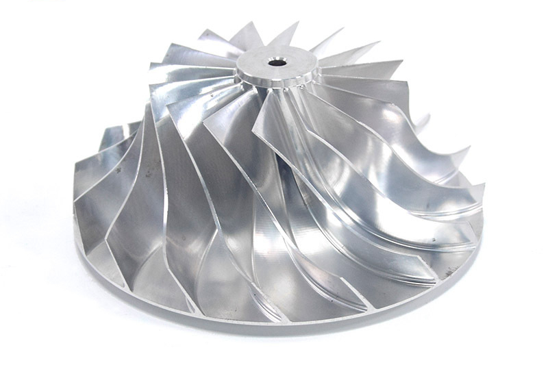
في أنظمة الشحن القسري عالية الأداء، يجب أن تتحمل المكونات درجات حرارة قصوى وضغوطًا عالية وإجهادًا دوريًا. تُعد سبائك إنكونيل المواد المفضلة لتصنيع الأجزاء الحرجة نظرًا لمتانتها الفائقة ومقاومتها للأكسدة واستقرارها الحراري. تختص Neway AeroTech في التشغيل الدقيق على آلات التحكم الرقمي لـ سبائك إنكونيل، لتقديم مكونات نظام الشحن القسري ذات التسامحات الدقيقة جدًا (±0.005 مم) وخصائص ميكانيكية فائقة.
باستخدام مراكز التشغيل المتقدمة متعددة المحاور على آلات التحكم الرقمي، واستراتيجيات الأدوات المُحسّنة، ومعايير الجودة من فئة الفضاء الجوي، نضمن أن أجزاء إنكونيل تلبي أكثر متطلبات أنظمة الشحن القسري صرامة لتطبيقات الفضاء الجوي وسباقات السيارات والصناعية.
التحديات الأساسية في تصنيع مكونات إنكونيل لأنظمة الشحن القسري
يُشكل تشغيل سبائك إنكونيل مثل إنكونيل 718 و إنكونيل 625 تحديات حرجة:
المتانة العالية والتوصيل الحراري المنخفض مما يتسبب في تآكل الأدوات السريع وتراكم الحرارة أثناء التشغيل.
تحقيق تسامحات أبعاد فائقة الدقة (±0.005 مم) لواجهات التحميل والتجميع الحرجة.
الحفاظ على نعومة سطحية دقيقة (Ra ≤0.8 ميكرومتر) لكفاءة الديناميكا الهوائية وتحسين التدفق.
إدارة التصلب بالعمل أثناء القطع يتطلب معلمات قطع واستراتيجيات مسار أداة مُحسّنة.
عملية التشغيل الدقيق على آلات التحكم الرقمي لمكونات إنكونيل
تتضمن عملية التشغيل الدقيق على آلات التحكم الرقمي لأجزاء الشحن القسري من إنكونيل:
تقييم المادة: تقييم البنية المجهرية والخصائص الميكانيكية لإنكونيل لتحديد معلمات التشغيل المثلى.
اختيار الأداة: استخدام أدوات كربيد أو سيراميك أو CBN مصممة خصيصًا لتشغيل السبائك الفائقة.
التشغيل متعدد المحاور على آلات التحكم الرقمي: التشغيل المتزامن على 4 أو 5 محاور لتحقيق أشكال هندسية معقدة وتقليل أخطاء إعادة الوضعية.
استراتيجيات التشغيل التكيفي: التحكم في الوقت الحقيقي لمعدلات التغذية وسرعات القطع (20–50 م/دقيقة) وعمق القطع لإدارة الحرارة وتعظيم عمر الأداة.
مراحل التشطيب السطحي: قطع تشطيب خفيفة لتحقيق نعومة سطحية Ra ≤0.8 ميكرومتر والحفاظ على سلامة الأبعاد.
التفتيش النهائي: أنظمة قياس CMM والقياس غير التلامسي للتحقق من تسامحات الأبعاد وامتثال النعومة السطحية.
مقارنة طرق التصنيع لأجزاء الشحن القسري من إنكونيل
طريقة التصنيع | دقة الأبعاد | النعومة السطحية (Ra) | مقاومة الإجهاد الحراري | سلامة السطح | الكفاءة التكلفية |
|---|---|---|---|---|---|
التشغيل الدقيق على آلات التحكم الرقمي | ±0.005 مم | ≤0.8 ميكرومتر | فائقة | ممتازة | متوسطة-عالية |
التشغيل بالتفريغ الكهربائي بالأسلاك | ±0.003 مم | ≤0.4 ميكرومتر | ممتازة | ممتازة | عالية |
التشغيل التقليدي | ±0.01 مم | ≤1.6 ميكرومتر | جيدة | جيدة | متوسطة |
استراتيجية اختيار طريقة التصنيع
يعتمد اختيار نهج التصنيع المناسب لأجزاء الشحن القسري من إنكونيل على التعقيد والتسامح والتطبيق:
التشغيل الدقيق على آلات التحكم الرقمي: مفضل لمعظم مكونات الشحن القسري عالية الأداء التي تتطلب أشكالًا هندسية معقدة ودقة قصوى (±0.005 مم) ونعومة سطحية فائقة.
التشغيل بالتفريغ الكهربائي بالأسلاك: مثالي للتطبيقات ذات التسامحات فائقة الدقة مع أشكال داخلية ضيقة ولكنه بشكل عام أبطأ وأكثر تكلفة.
التشغيل التقليدي: مناسب للأشكال الهندسية الأبسط حيث تكون التسامحات حول ±0.01 مم مقبولة ويكون التحكم في تكلفة الإنتاج أولوية.
مصفوفة أداء سبائك إنكونيل
مادة السبيكة | أقصى درجة حرارة خدمة (°C) | قوة الشد (MPa) | مقاومة الإجهاد الحراري | مقاومة الأكسدة | التطبيقات النموذجية |
|---|---|---|---|---|---|
700 | 1375 | ممتازة | فائقة | أعمدة شاحن توربيني، علب التوربين | |
815 | 965 | جيدة | فائقة | مشعبات العادم، علب الضاغط | |
950 | 1200 | فائقة | ممتازة | عجلات توربين عالية الحرارة | |
900 | 1150 | ممتازة | فائقة | فوهات التوربين، مكونات القسم الساخن |
استراتيجية اختيار السبيكة لمكونات الشحن القسري
يضمن اختيار سبيكة إنكونيل المناسبة الأداء الميكانيكي والحراري المطلوب:
إنكونيل 718: الخيار الأفضل للأعمدة الدوارة والعلب التي تتطلب قوة إجهاد عالية وتعمل حتى 700°C.
إنكونيل 625: مفضل لمكونات نظام الضاغط والعادم المعرضة لدرجات حرارة تصل إلى 815°C، ويوفر مقاومة فائقة للتآكل والأكسدة.
إنكونيل 713C: مثالي لتطبيقات عجلة التوربين التي تتطلب قوة شد عالية (1200 MPa) ومقاومة ممتازة للإجهاد الحراري حتى 950°C.
إنكونيل 939: يُختار لمكونات القسم الساخن التي تتطلب مقاومة للزحف وقوة ميكانيكية تحت التشغيل المستمر عند 900°C.
تقنيات المعالجة اللاحقة الرئيسية
تعزز المعالجة اللاحقة جودة الجزء وأدائه:
التشطيب السطحي الدقيق: الطحن والتلميع لتحقيق Ra ≤0.8 ميكرومتر.
المعالجة الحرارية: معالجات المحلول والشيخوخة لتعظيم الخصائص الميكانيكية.
الكبس متساوي الحرارة الساخن (HIP): يكثف المادة لإزالة المسامية الداخلية.
الطلاءات الواقية: تطبيق طلاءات مقاومة للأكسدة والتآكل للحماية في البيئات القاسية.
طرق الاختبار وضمان الجودة
تخضع جميع الأجزاء المشغولة على آلات التحكم الرقمي من إنكونيل للتحقق الصارم:
آلة القياس الإحداثي (CMM): تفتيش دقة الأبعاد ضمن ±0.005 مم.
التفتيش بالأشعة السينية: تحليل سلامة داخلية غير مدمر.
المجهر المعدني المجهري: تقييم هيكل الحبيبات.
اختبار الشد: التحقق من القوة الميكانيكية.
تلتزم عملية بأكملها بمعايير جودة الفضاء الجوي المعتمدة AS9100.
دراسة حالة: أعمدة شاحن توربيني من إنكونيل 718 المشغولة على آلات التحكم الرقمي
أنتجت Neway AeroTech أعمدة شاحن توربيني دقيقة من إنكونيل 718 لتطبيقات السباقات عالية الأداء، محققة:
درجة حرارة التشغيل: تصل إلى 700°C خدمة مستمرة
دقة الأبعاد: ±0.005 مم محافظة عليها باستمرار
النعومة السطحية: Ra ≤0.6 ميكرومتر بعد مراحل التشطيب
الشهادة: متوافقة بالكامل مع معايير جودة الفضاء الجوي AS9100
الأسئلة الشائعة
لماذا تُعد سبائك إنكونيل مثالية لمكونات نظام الشحن القسري؟
ما التسامحات الدقيقة التي يمكن تحقيقها مع الأجزاء المشغولة على آلات التحكم الرقمي من إنكونيل؟
كيف تدير Neway AeroTech تآكل الأدوات عند تشغيل إنكونيل؟
ما درجات إنكونيل الموصى بها لأعمدة وعلب شاحن التوربين؟
ما إجراءات ضمان الجودة التي تضمن موثوقية مكونات إنكونيل؟
