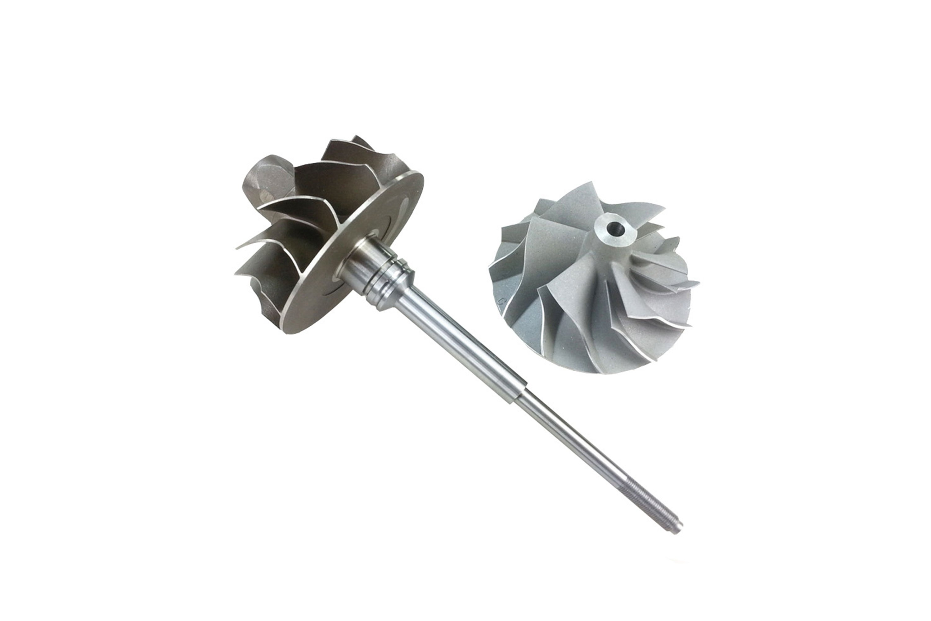
TMS-75 Superalloy Directional Casting Hot Section Engine Parts
Introduction
Hot section engine parts—including turbine vanes, blades, combustor hardware, and transition ducts—operate under extreme temperatures, oxidation, and thermal fatigue in both aerospace and power turbine systems. These components demand materials with high creep strength, oxidation resistance, and microstructural stability. TMS-75, a third-generation nickel-based superalloy developed for single crystal and directional solidification, is designed for superior high-temperature strength and reduced thermal conductivity, making it ideal for hot section applications.
At Neway AeroTech, we specialize in directional casting of TMS-75 components using advanced vacuum investment casting, spiral grain selectors, and precision withdrawal control. Our castings serve critical aerospace, power generation, and defense applications requiring long-life components in thermally aggressive environments.
Core Technology of TMS-75 Directional Casting for Hot Section Components
Wax Pattern Fabrication Wax patterns for blades, vanes, and liner segments are molded to ±0.05 mm accuracy, ensuring aerodynamic and sealing surface integrity.
Shell Mold Construction High-strength ceramic shell molds (6–10 mm) are built to handle directional solidification temperatures and maintain structural support during withdrawal.
Grain Selector Integration Spiral or starter selectors guide [001] grain growth along the part's main stress axis, minimizing grain boundary formation.
Vacuum Induction Melting TMS-75 is melted under vacuum (≤10⁻³ Pa) at ~1450°C, ensuring chemical purity and minimizing segregation.
Directional Solidification The mold is withdrawn at 2–4 mm/min through a tightly controlled thermal gradient to produce columnar [001]-oriented grains.
Shell Removal and Surface Cleaning Shells are removed using high-pressure blasting and chemical leaching, preserving intricate cooling features and wall definition.
Heat Treatment and Aging Solution and aging treatments refine γ′ phase distribution and stabilize the microstructure for long-term service.
Final Machining and Inspection Components are finished via CNC machining, EDM, and validated through CMM and X-ray inspection.
TMS-75 Material Properties for Directionally Cast Engine Parts
Max Operating Temperature: ~1150°C
Tensile Strength: ≥1250 MPa
Creep Rupture Strength: ≥250 MPa at 1100°C (1000 hrs)
Thermal Conductivity: Lower than CMSX-4, improving thermal barrier performance
Gamma Prime Content: ~70%
Oxidation Resistance: Excellent in combustion gas environments
Grain Structure: Columnar [001], deviation <2° verified via EBSD
Case Study: TMS-75 Turbine Vanes and Transition Segments for Military Jet Engine
Project Background
Neway AeroTech manufactured first-stage vanes and combustor interface segments from TMS-75 for a next-generation military jet engine. The customer required high creep resistance, directional grain control, and consistent thermal fatigue performance under conditions exceeding 1100°C.
Applications
Turbine Nozzle Guide Vanes Fixed airfoils subjected to aerodynamic loading and thermal gradients.
Combustor Transition Segments Thin-wall ducting elements with vibration exposure and rapid temperature cycling.
Liner Segments and Baffles Shield internal engine structure from hot gas exposure and require oxidation resistance.
Seal Segments and Shrouds Static parts that demand sealing integrity and high-temperature creep performance.
Manufacturing Workflow at Neway AeroTech
Simulation-Based Mold Design CFD and solidification modeling guide selector placement, gating, and chill orientation for stable [001] growth.
Vacuum Casting Execution Directional casting is performed under vacuum, with controlled withdrawal rates for uniform grain alignment and defect avoidance.
Heat Treatment and Microstructural Optimization Post-casting heat treatments promote uniform γ′ distribution and long-term stability under load.
Precision Machining and Inspection CNC and EDM machining ensure dimensional compliance, followed by CMM and EBSD validation.
Key Manufacturing Challenges
Maintaining grain alignment in complex curved geometries
Preventing hot tears and grain boundary migration in thin-wall areas
Balancing cooling rate and microstructure stability
Controlling deformation during post-casting heat treatment
Results and Verification
[001] orientation confirmed across all parts with <2° deviation via EBSD
Creep strength exceeded 250 MPa at 1100°C
Zero porosity confirmed post-casting via ultrasonic and radiographic NDT
Dimensional tolerance held within ±0.03 mm
Full traceability and AS9100 documentation provided
FAQs
Why is TMS-75 used in directional casting for hot section parts?
What are the thermal and mechanical limits of TMS-75?
How is grain orientation controlled during directional solidification?
What quality certifications support TMS-75 component production?
Can TMS-75 components be repaired or field welded?

