Superalloy CNC Machining for Aerospace Turbine Rotor Components
As global aerospace propulsion programs push for higher thrust-to-weight ratios and thermal efficiency, the demand for precision-machined superalloy turbine components continues to rise. In 2024, the aerospace CNC machining sector alone exceeded USD 5.3 billion, with turbine rotors accounting for over 32% of high-temperature alloy usage.
Neway AeroTech delivers critical solutions in this domain. Our advanced CNC machining of Inconel, Rene, and Nimonic alloys enables superior dimensional stability, fatigue resistance, and performance for turbine rotors operating above 15,000 rpm and 1000°C.
Core Technology of Superalloy CNC Machining
Superalloy CNC machining at Neway AeroTech combines precision, thermal stability, and tool life optimization technologies for extreme applications.
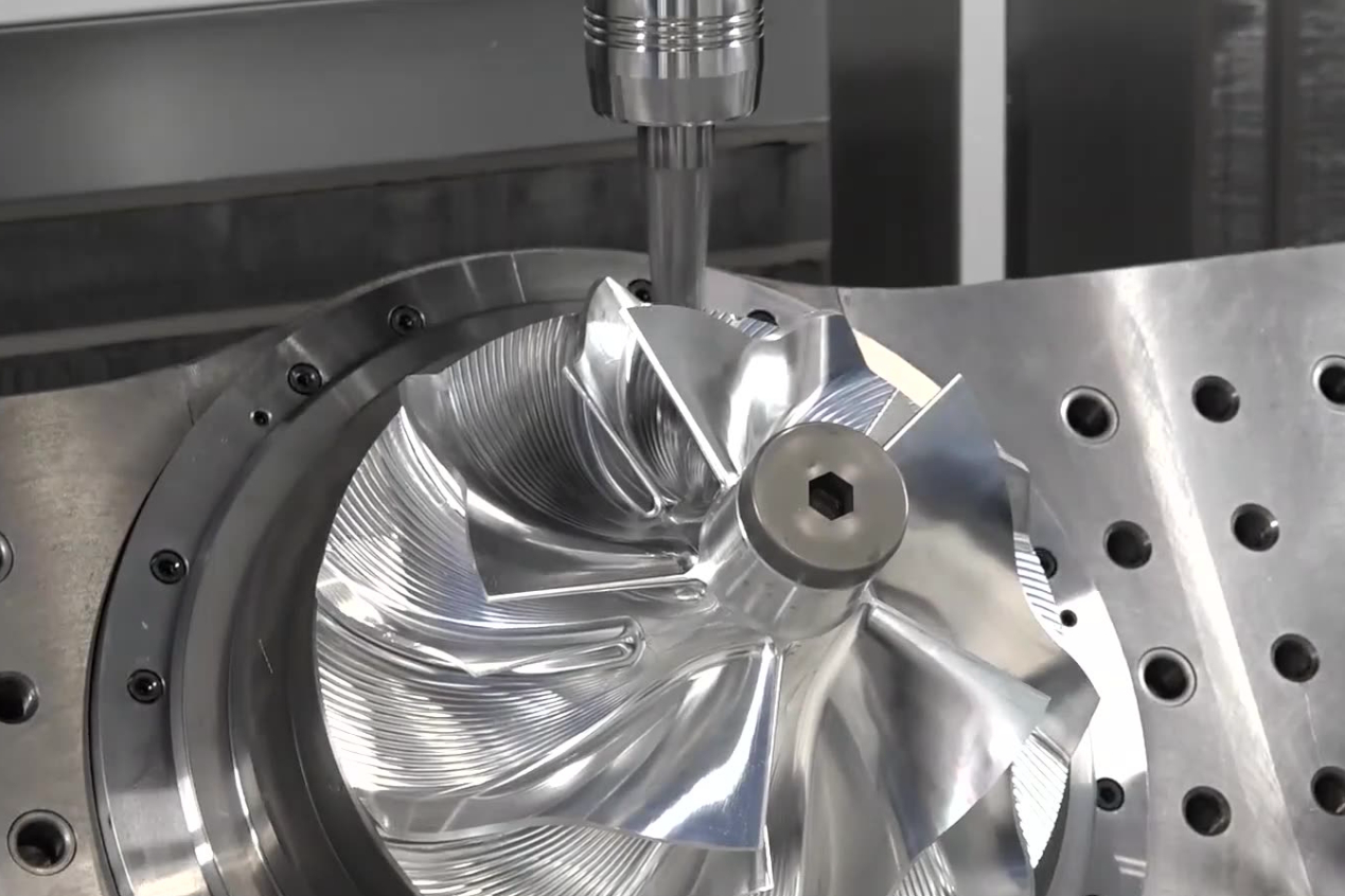
5-axis CNC machining enables complete tool access for complex contours and deep cavity superalloy turbine components.
Tool wear compensation algorithms ensure dimensional repeatability for extended operations under abrasive alloy contact conditions.
High-pressure through-spindle coolant systems reduce heat buildup and improve cutting efficiency in tough superalloy materials.
Post-process CMM and SEM inspection guarantees compliance with micron-level tolerances and aerospace-grade specifications.
All machining operations comply with aerospace standards such as AS9100D and NADCAP, ensuring consistent precision down to ±5 μm tolerances.
Typical Superalloy in CNC Machining
The following superalloys are commonly used for turbine rotor components:
Alloy | Max Service Temp (°C) | Tensile Strength (MPa) | Application |
|---|---|---|---|
704 | 1240 | Rotor disks, turbine hubs | |
980 | 1450 | Turbine blades, rotors | |
920 | 1265 | Compressor rotors | |
1140 | 1000 | Turbine vane roots |
Each alloy offers specific advantages in creep resistance, fatigue life, and oxidation protection under extreme conditions.
Case Study: Turbine Rotor Components CNC Machining
Project Background
An aerospace propulsion client required CNC machined Inconel 718 rotor disks for a next-generation military turbofan engine. The component demanded a profile tolerance within ±0.01 mm and concentricity less than 0.008 mm. The outer geometry featured undercuts, deep cavities, and bore alignment tolerances tighter than ISO H6.
Typical Turbine Rotor Component Models and Applications
Model | Application | Material | Max RPM | Description |
|---|---|---|---|---|
TRD-950 | Jet Engine High-Pressure Rotor | Inconel 718 | 18,000 | Precision balancing, multi-hole hub |
LPT-420 | Low-Pressure Turbine Disc | Rene 88 | 12,000 | Stress-relieved, profile-milled |
CPT-180 | Compressor Rotor | Nimonic 90 | 16,000 | Lightweight blisk-style design |
These parts are integral to engine modules across aviation platforms such as F-class turbines, advanced UAVs, and supersonic jets.
CNC Machining Challenges of Turbine Rotor Components
Tool wear exceeds 0.05 mm/hour due to alloy hardness above 40 HRC and aggressive edge geometry requirements.
Thermal distortion exceeds 0.02 mm during continuous operations over 2 hours at cutting speeds beyond 150 m/min in superalloy surfaces.
Bore and shaft alignment tolerances below 8 μm demand ultra-precise probing and multi-step tool path correction methods.
Residual stress of up to 450 MPa must be relieved after roughing to prevent warping during finishing passes.
Chip evacuation in cavities deeper than 8×D requires optimized flute geometry and coolant pressure exceeding 80 bar.
Turbine Rotor Components CNC Machining Solutions
Cryogenic machining at -196°C using liquid nitrogen reduced tool wear by 25% and improved surface integrity significantly.
Adaptive roughing toolpaths with trochoidal milling minimized tool pressure and reduced cycle times by approximately 18% across multiple cavity profiles.
On-machine probing with 3D scanning ensured bore alignment accuracy within 6 μm and reduced human inspection intervention by 60%.
Hot Isostatic Pressing (HIP) at 1030°C and 100 MPa eliminated 98% internal porosity before final finish machining.
GDMS alloy validation confirmed elemental consistency within ±0.03 wt% prior to machining to ensure mechanical performance under 1000°C operating temperatures.
Results and Verification
Manufacturing: Rotor disks were machined on 5-axis machining centers achieving dimensional accuracy within ±5 μm and roundness of 0.007 mm, maintaining balance for 18,000 rpm operational speeds with concentricity TIR under 0.006 mm.
Finishing: Surface roughness was reduced to Ra 0.4 μm using diamond finishing tools with controlled feed of 0.02 mm/rev and optimized spindle speed of 1800 rpm, improving fatigue life significantly.
Post-Processing: HIP treatment at 1030°C and 100 MPa for 4 hours eliminated voids and restored isotropic grain structure, ensuring mechanical strength retention at 980°C service temperatures.
Testing: CMM inspection confirmed 100% tolerance compliance; X-ray, SEM, and GDMS analysis verified material uniformity, with fatigue tests showing 1.5× longer service life than the client’s baseline requirement.
FAQs
What are the typical tolerances achievable for CNC machined turbine rotors?
How do you handle residual stress in thick-section superalloy parts?
What certifications are required for aerospace rotor part suppliers?
Can you machine both single-crystal and equiaxed superalloy components?
How do you ensure bore-to-hub concentricity for critical rotor disks?
