Precision CNC Machining of Superalloy Turbine Blade Components
High-Tolerance Manufacturing for Advanced Turbine Systems
Turbine blade components made from superalloys are subjected to extreme thermal, mechanical, and corrosive stresses. These blades—used in gas turbines, jet engines, and power generators—require micron-level precision, aerodynamic consistency, and fatigue-resistant geometry. Achieving this demands specialized CNC machining combined with advanced tooling and metrology systems.
Neway AeroTech specializes in 5-axis precision CNC machining of superalloy turbine blades, using cast or forged parts from Inconel 738, Rene 88, CMSX-4, and Hastelloy X.
Core Technologies for Turbine Blade CNC Machining
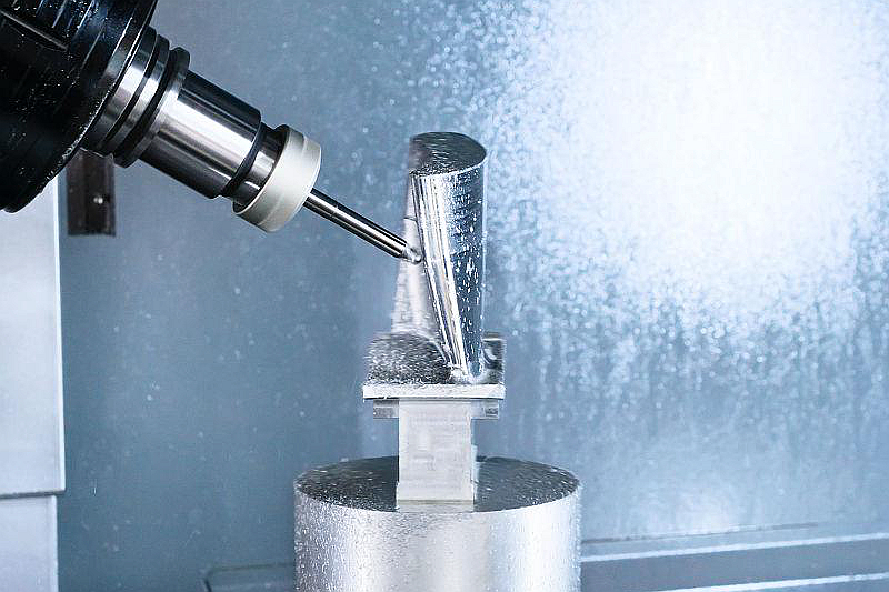
Turbine blade machining involves high-speed contouring and precision finishing across multiple profiles and section depths.
5-axis simultaneous CNC machining for blade twist and camber control
Ball-end and barrel tools for smooth trailing and leading edges
High-pressure coolant-through spindle for tool life and chip evacuation
Tool path optimization using CFD-generated CAD profiles
All operations comply with AS9100D and turbine engine OEM specifications.
Common Superalloys for Turbine Blade Machining
Alloy | Max Temp (°C) | Yield Strength (MPa) | Blade Application |
|---|---|---|---|
1050 | 880 | High-pressure stator blades | |
980 | 1450 | Turbine rotors and vanes | |
1140 | 980 | First-stage turbine airfoils | |
1175 | 790 | Combustor guide vanes |
These alloys offer oxidation resistance, strength retention, and thermal fatigue durability in engine hot sections.
Case Study: CNC Machining of CMSX-4 First-Stage Blade Set
Project Background
A turbine manufacturer required 5-axis CNC finishing of CMSX-4 single crystal blades with complex cooling hole geometry and platform features. Target tolerances: ±0.008 mm on airfoil profiles, Ra ≤ 0.4 μm surface finish, and full-length trailing edge radius of 0.2 mm.
Typical Turbine Blade Component Models and Applications
Component | Material | Max Temp | Feature | Industry |
|---|---|---|---|---|
HP Rotor Blade | Rene 88 | 980°C | Multi-cooling hole platform | |
NGV Segment | Inconel 738 | 1050°C | Shroud, vane, and seal fin | |
First-Stage Airfoil | CMSX-4 | 1140°C | 3D twist and root lock | |
Guide Vane | Hastelloy X | 1175°C | Tapered cross-section |
Each part is verified for structural stability and aerodynamic precision post-machining.
CNC Machining Challenges in Superalloy Blade Production
Tool wear exceeds 0.1 mm/hour due to high hardness alloys above 40 HRC and abrasive carbide-resistant microstructures.
Ra ≤ 0.4 μm surface finish is required on airfoil surfaces to minimize aerodynamic drag and boundary layer turbulence.
Profile deviation must stay <0.01 mm across the full 3D twist of the blade airfoil to meet aerodynamic specifications.
Root and platform geometry tolerances must be held within ±0.008 mm for secure dovetail or fir-tree fitment.
Edge blending on cooling holes must ensure radii under 0.2 mm with no local material thinning or deformation.
CNC Machining Solutions for Turbine Blade Airfoils
CAM toolpaths use CFD data to achieve ±0.008 mm accuracy across the entire airfoil surface and profile transition.
High-speed machining with barrel tools maintains Ra ≤ 0.4 μm surface finish on trailing edges and leading contours.
In-process probing every 15 minutes corrects tool wear to hold geometric accuracy within ±0.005 mm on vane profiles.
CNC ground tooling radius ±0.01 mm enables consistent root-lock machining for tight dovetail fit and stress distribution.
5-axis alignment for EDM holes ensures 0.2 mm radii without backwall thinning or micro-crack initiation near the exit.
Results and Verification
Manufacturing Methods
Parts were first cast via vacuum investment casting, followed by stress relief and initial surface prep. Final 5-axis CNC milling produced airfoil contours within ±0.008 mm and 0.2 mm edge radii.
Precision Finishing
Polishing, groove blending, and EDM finishing ensured Ra ≤ 0.4 μm. Cooling hole deburring was conducted with micro tools and ultrasonic flushing.
Post-Processing
Parts underwent HIP and full heat treatment. Optional TBC coatings applied to select surfaces based on client specs.
Inspection
CMM inspection verified airfoil form within 5 μm tolerance. X-ray testing confirmed structural integrity. SEM analysis validated surface quality and microstructure.
FAQs
What is the standard tolerance for airfoil profile machining?
How are internal cooling holes handled during CNC machining?
What is the typical surface finish achieved for turbine blade machining?
Can you combine EDM and CNC for blade finishing?
What materials are most commonly used for high-pressure turbine blades?
