Which Datum Should a Vacuum Cast Casing Be Machined From?
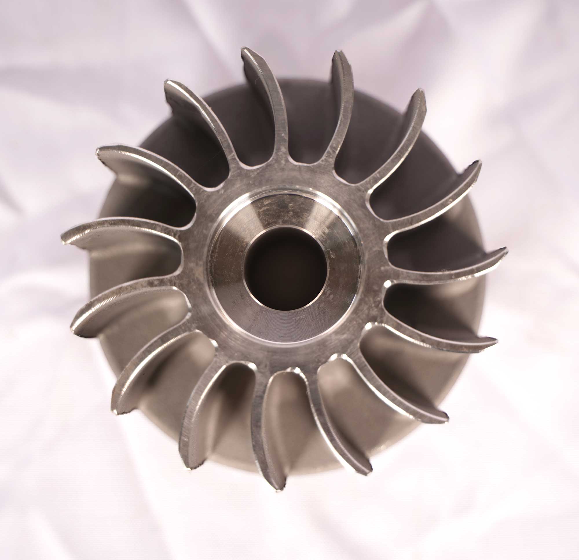
Set the vacuum cast casing datum on the large-end flange face and the bore axis, then machine in one setup to hold ⌀0.10 mm. The eight flange holes and the boss bore are cut from it in a single clamping. A second setup re-clamps the 2.5 mm wall and adds position error before the first cut is taken.
Why does casing machining start at the flange face?
The flange face is the only surface on a 2.5 mm wall casing that is large enough to locate on and flat enough to repeat. It also carries the sealing function, so any error in that face appears directly at assembly. Machining starts there and works inward.
The face sets axial location as well. Length from the large flange to the small-end spigot is measured from it, and the ⌀61.5 +0.3/+0.1 spigot is turned from the same axis. A datum error at the flange shifts every downstream dimension by the same amount.
Castings arrive with 1.0 mm of stock on that face and 0.4 mm on the hole diameters. That stock absorbs solution-treatment warp without cutting into the 2.2 mm minimum wall. A datum that consumes the stock on the first pass leaves nothing to correct with.
The vacuum cast casing datum holds eight holes within ⌀0.10 mm
The blank sits with the flange face on three points and the bore on a self-centering fixture; that pair is the vacuum cast casing datum, set once per part. Drilling, boring and the boss cut all run in that clamping. Position tolerance for the eight ⌀8.9 holes is ⌀0.10 mm, measured from the same datum the machine used.
The boss bore at ⌀24 +0.4/0 is cut in the same clamping rather than after a re-chuck. Cutting it together with the flange holes removes the eccentricity that a second location would add, and it keeps the bore axis square to the sealing face.
Verification follows the cut, not the drawing alone. A coordinate measuring machine checks flatness at 0.05 mm, bore roundness at 0.05 mm and hole position at ⌀0.10 mm on every part, with the datum reference frame stated on the report per ASME Y14.5. CMM checking against a stated datum is what makes those numbers comparable between parts and between suppliers.
Second setup adds 0.2 mm of hole position error
Position error enters at the second clamping. Releasing the vacuum cast casing datum to re-chuck a conical wall moves the bore by up to 0.2 mm unless clamp force is controlled, and the movement appears at the far end of the feature rather than at the clamp itself.
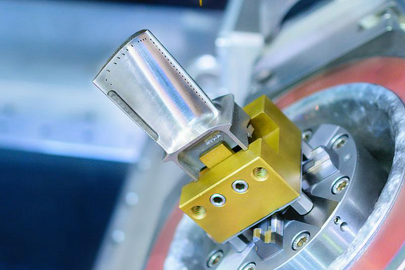
Two setups also mean two datum references, and the tolerance stack then runs through the fixture twice. Turbine component datum planning follows the same rule: locate on the surface the finished part will sit on, and keep the number of setups to one wherever the geometry allows.
Fixture repeatability decides whether a second setup is even worth quoting. If the fixture repeats to 0.03 mm, the stack may still close; if it repeats to 0.10 mm, the second setup consumes the whole hole tolerance before any cutting error is added.
Feature | Target | Unit |
|---|---|---|
Flange face flatness | 0.05 | mm |
Flange hole position (8× ⌀8.9) | ⌀0.10 | mm |
Spigot roundness (⌀61.5 +0.3/+0.1) | 0.05 | mm |
Boss bore (⌀24 +0.4/0) | 0.02 | mm |
Face stock left on blank | 1.0 | mm |
Hole diameter stock | 0.4 | mm |
Minimum wall after cleanup | 2.2 | mm |
When does the one-setup datum stop working?
The one-setup datum stops working when the blank is too far out of position to clean up. Cast eccentricity above 0.4 mm, or heat-treatment distortion above 0.30 mm, leaves too little stock on one side of the wall. Such a part is straightened or re-datumed before cutting rather than forced through the original setup.
Clamp force is the second limit. A wall that deflects under clamping springs back after release, so position reads well on the machine and out of tolerance on the plate. Light clamping plus support on the cone avoids most of that movement.
A third limit is wall thickness itself. If the wall reaches 2.2 mm only after the stock is removed, there is no room left for a correction pass, and the datum question becomes a castability question instead.
Send the drawing with its datum callouts and stock allowances, and we will return a machining plan with setup and inspection points under our Superalloy CNC Machining route before quoting.