Superalloy Welding: Boost Strength and Lifespan of Components
Welding does not automatically boost the strength or lifespan of a superalloy component. It creates a joint, build-up, or repair zone with fusion metal, a heat-affected zone, residual stress, and a different thermal history from the parent material. Whether that zone is acceptable must be demonstrated against a defined baseline and failure mechanism.
For this RFQ, buyers should state the required parent and joint properties, service temperature, load spectrum, environment, joint efficiency or design basis, failure location of concern, qualification specimen geometry, production inspection, and responsibility for life assessment. The manufacturing supplier can provide process and test evidence; service-life approval remains with the responsible engineering authority.
Define What “Strength” and “Lifespan” Mean for the Joint
Tensile strength, yield strength, ductility, hardness, fracture behavior, creep, stress rupture, low-cycle fatigue, high-cycle fatigue, thermal-mechanical fatigue, oxidation, corrosion, and coating durability are different outcomes. A passing room-temperature tensile result does not establish high-temperature creep or cyclic life.
Describe operating stress, temperature range, dwell, startup and shutdown, vibration, pressure, atmosphere, coating, contact, and inspection interval. Identify whether failure is expected in weld metal, heat-affected zone, fusion boundary, parent material, machined toe, repaired surface, or a location outside the joint.
State the acceptance source. It may be a drawing, material specification, approved procedure, design allowable, joint-efficiency requirement, qualification test plan, or engineering disposition. Published alloy data cannot be applied directly to a production weld with different filler, dilution, geometry, heat treatment, and surface condition.
Establish a Parent-Material and As-Welded Baseline
A claim of improvement needs a comparator. Define whether the baseline is unwelded parent material, an un-repaired casting, a previous procedure, as-welded condition, PWHT condition, or service-exposed material. Record alloy heat, product form, grain structure, prior heat treatment, section, orientation, and specimen preparation.
For repair studies, characterize the incoming defect and material before excavation. Coating residue, oxidation, depletion, prior blending, embedded contamination, crack branching, and service aging can affect results. A repair coupon cut from new plate may not represent the service-exposed casting.
Preserve raw baseline data and specimen maps. Testing only the final welded condition can show whether it meets an absolute limit, but it cannot show what welding changed or which process step produced the change.
Use a Qualification Matrix That Represents Production
Production variable | Qualification coverage | Why it affects evidence |
Base and filler alloy | Exact grade, condition, heat or lot controls | Chemistry, cracking and thermal response |
Joint or repair geometry | Groove, thickness, gap, penetration, repair depth | Heat flow, dilution, restraint and defect modes |
Welding process and position | Energy source, parameter range, orientation, access | Fusion shape and repeatability |
Fixture and restraint | Representative clamp and sequence | Residual stress, mismatch and cracking |
Thermal route | Preheat, interpass, PWHT and later cycles | HAZ, precipitates, stress and dimensions |
Final surface | Machined, blended, peened or coated condition | Fatigue initiation and inspection sensitivity |
Choose worst-case combinations rather than an easy coupon. Maximum and minimum thickness, deepest approved repair, difficult access, start-stop zone, high restraint, dissimilar joint, and coating restoration may need separate coverage. Define what variables invalidate or extend qualification.
A flat butt-weld coupon is useful for procedure development but may not represent a thin curved wall, airfoil, tube attachment, seal repair, variable-thickness casting, or service-aged component. Use representative features or staged demonstrations when geometry changes the process footprint.
Map Specimens to Weld Metal, HAZ, and Parent Material
Every destructive specimen should be located on a drawing or section map. Identify weld centerline, fusion boundary, heat-affected zone, parent material, surface and root, build direction for multi-layer repairs, base-material grain orientation, and test axis.
Transverse tensile specimens often include multiple zones and may fail in the weakest or smallest net section. All-weld-metal specimens answer a different question. Creep, fatigue, and fracture specimens can be highly sensitive to notch location, surface condition, residual stress, and alignment. State which region the test is intended to challenge.
Separately prepared coupons should travel through the same filler, welding parameters, PWHT, machining, peening, and coating cycle where those steps affect results. If production parts and coupons follow different routes, document the difference and its representation limit.
Use Metallography and Hardness to Explain the Joint
Macroetch sections can show penetration, fusion profile, root condition, undercut, reinforcement, lack of fusion, and gross porosity. Metallography can evaluate solidification structure, HAZ condition, cracks, liquation, precipitates, carbides, diffusion zones, oxide, and repair-layer interfaces at selected locations.
A hardness traverse can identify strong gradients or unexpected local conditions, but hardness alone does not establish creep, fatigue, ductility, or environmental behavior. Define method, load, spacing, locations, surface preparation, and acceptance or comparison basis.
Use microstructural evidence to explain mechanical results. If a specimen fails early, connect the fracture location with fusion shape, HAZ structure, inclusion, pore, surface feature, hardness, filler dilution, and thermal history rather than reporting only the final load.
Separate NDE Acceptance from Property Validation
Visual inspection, FPI, radiography, CT, and ultrasonic methods can detect selected workmanship or defect conditions. They do not directly measure tensile, creep, fatigue, or oxidation performance. A weld can pass NDE and still have an unsuitable microstructure or joint design; a mechanical coupon can pass while a production part contains an unacceptable indication.
Define NDE method, revision, acceptance class, coverage, timing, surface condition, sensitivity, operator requirements where applicable, and report content. Inspect preparation or excavation before filler hides the root, then inspect after welding, PWHT, machining, and other operations that can expose or obscure indications.
Use NDE to maintain production consistency against the qualified envelope. Do not use it to claim a service interval that was never evaluated.
Select Mechanical Tests from the Failure Mechanism
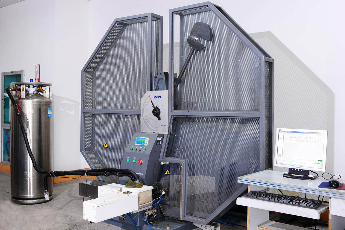
Room- and elevated-temperature tensile tests can evaluate strength and ductility under monotonic loading. Creep and stress-rupture tests address time-dependent high-temperature deformation or failure. Fatigue methods address cyclic loading, while thermal-mechanical fatigue includes coupled strain and temperature cycles. Fracture or bend tests answer other joint questions.
State test standard, temperature, environment, stress or strain control, waveform, frequency, dwell, ratio, runout, specimen geometry, orientation, surface condition, quantity, and statistical or acceptance treatment. Results without these conditions cannot be compared responsibly.
Use material testing and analysis selectively. More test types do not automatically create better evidence; the right tests must represent the design question and qualified process range.
Evaluate PWHT as a Controlled Variable, Not a Cure-All
PWHT can alter residual stress, precipitate condition, hardness, ductility, crack sensitivity, and dimensions. The effect depends on base and filler alloy, welding heat input, prior condition, ramp, soak, cooling, and subsequent thermal exposure.
Compare as-welded and PWHT conditions during procedure development when the engineering question requires it. A cycle that improves one tensile or hardness result may not optimize creep, fatigue, or coating compatibility. Review cumulative heat treatment, HIP, brazing, and coating diffusion history.
After PWHT, repeat required NDE and dimensional inspection. Delayed or strain-age cracking can appear during thermal processing, and distortion can alter final machining stock. The furnace chart should link to the same specimen and production identities.
Include Surface Condition and Residual Stress in Fatigue Evidence
Fatigue often initiates at weld toe geometry, root mismatch, undercut, grinding marks, recast, blend transitions, pores open to the surface, coating damage, or tensile residual stress. Test specimens should represent the approved final surface when the surface is part of the production route.
Grinding and blending can remove stress concentrators but can also reduce wall, introduce scratches, or hide an unacceptable excavation. Peening may create compressive surface stress when controlled, but later machining or heat treatment can remove or relax that condition. Record the sequence.
Residual-stress measurement may support development for critical cases, but method, depth, location, and uncertainty must be defined. Do not convert one local reading into a general component-life claim.
Test Environmental Compatibility Where It Governs
Weld metal and HAZ chemistry can respond differently from parent material in oxidation, hot corrosion, carburization, sulfidation, or process media. Dissimilar filler, dilution, segregation, and coating restoration can create local behavior not represented by parent-alloy data.
If environment is a release or qualification driver, define exposure temperature, gas or media composition, pressure, time, cycling, specimen surface, coating, and evaluation method. Weight change, scale morphology, penetration, cracking, and mechanical-property retention answer different questions.
Where a coating is restored over a weld repair, evaluate substrate preparation, bond or interface, thermal cycle, coverage, passage protection, and inspection. A successful bare-weld test does not automatically qualify the coated system.
Set a Clear Boundary for MRO Life Extension
A repaired service component contains prior creep, fatigue, oxidation, coating loss, wear, deformation, and possible overheating. Welding can address an approved local condition; it does not erase accumulated damage elsewhere or restore the part to a new-material baseline.
Define used-sample condition, incoming NDE, destructive evaluation if permitted, minimum wall, repair zones, maximum cycles, PWHT limits, coating restoration, and final acceptance. Configuration and design authority must be established for non-OEM work. The physical sample is not a complete design specification.
Life or interval decisions should combine manufacturing evidence with stress analysis, operating history, damage tolerance, inspection capability, and maintenance policy under the responsible authority. The supplier should report what was processed and measured without extending the conclusion beyond the data.
Monitor Production Against the Qualified Envelope
Freeze base and filler material, joint design, procedure revision, parameters, fixture, operator or automation requirements, heat treatment, machining, surface process, NDE, and sampling at the level required by qualification. Define change-notification and requalification triggers.
Trend indications, repair rate, location, distortion, hardness, metallographic findings, and production test results. A trend toward one defect or feature can reveal drift before final failure. Connect each result to part, lot, filler, procedure, and equipment record.
Production coupons should have a stated purpose and frequency. They may monitor chemistry, process setup, or properties, but should not be treated as full requalification unless the plan says so.
Prepare an Evidence-Based Welding RFQ
Send the controlled drawing and model, base and filler materials, joint or repair map, material condition, service load and temperature, governing failure mechanism, required joint properties, qualification matrix, specimen map, PWHT, machining and surface condition, NDE, mechanical and environmental tests, quantities, first-article scope, records, and change control.
Ask suppliers to separate procedure development, representative hardware, destructive specimens, welding, PWHT, machining, NDE, metallography, mechanical tests, environmental tests, documentation, and recurring monitoring. Require assumptions and representation limits.
A defensible proposal will state what evidence shows the joint meets its requirement and what remains outside the supplier's conclusion. That is the correct way to discuss strength and lifespan without turning a manufacturing process into an unsupported performance promise.
Related FAQs
What Advantages Does Welding Superalloys Offer Over Traditional Metals?
How Does PWHT Enhance Performance of Welded Superalloy Components?
Weld Integrity Tests: NDT, Metallography, and Fatigue Validation for Superalloys
Most Welded Superalloys in Power Generation: Inconel 617, 625, 718, and Hastelloy X
Which Tests Verify the Performance of Welded Superalloy Parts?
How Welding Affects Superalloy Mechanical Properties: Strength, Cracking, and Fatigue