Stress Relief Techniques in High-Temp Alloy Castings
Stress relief for a high-temperature alloy casting is a route decision, not a default furnace step. Residual stress can come from nonuniform solidification and cooling, gate removal, straightening, blasting, weld repair, rough machining, drilling, or EDM. The buyer and supplier should identify the dominant source, the geometry at risk, the approved alloy condition, and the next manufacturing operation before selecting a treatment.
The objective is controlled dimensional and material behavior, not a promise that every stress is removed. A thermal or mechanical technique can also move the part, alter material condition, consume thermal exposure, or conflict with later solution treatment, aging, joining, and coating. The RFQ should define the starting condition, allowed technique, critical datums, verification, and approval authority.
Locate Residual-Stress Sources in the Manufacturing Route
Map the route from wax and shell through pouring, knockout, gate removal, thermal processing, machining, joining, coating, and final inspection. Mark operations that create strong thermal or mechanical gradients. A heavy hub beside a thin wall can cool differently after casting; removing a gate from one side can release restraint; rough machining a bore can unbalance a ring; weld repair can introduce a local heat-affected condition.
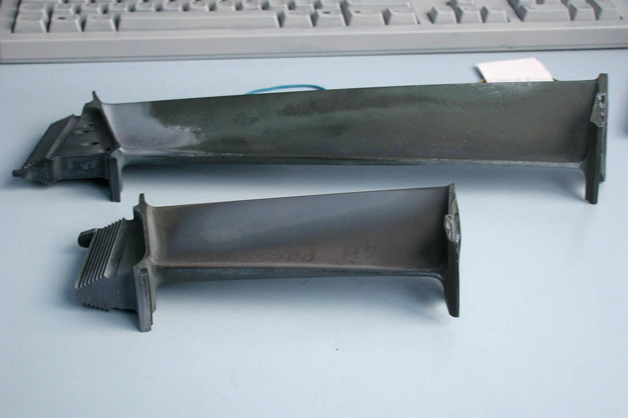
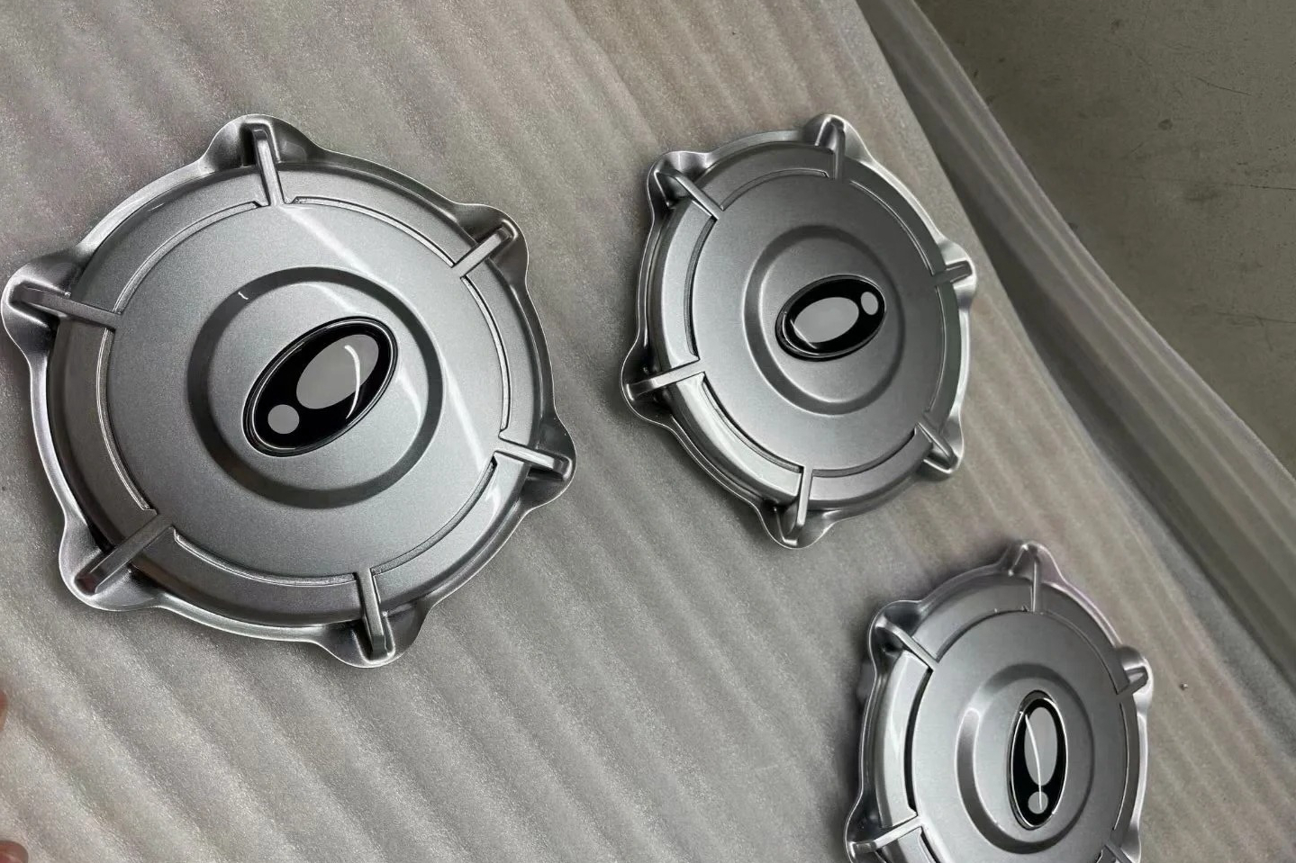
Component geometry determines the visible symptom. A ring may change roundness, a long casing may bow, a flange may lose flatness, an impeller may shift runout, and a thin vane segment may move at mounting features. The drawing should identify which relationships matter at the next setup instead of asking the supplier to report only overall length and width.
Record when distortion first appears. Measurements after casting cleanup, after heat treatment, after rough machining, and after joining can distinguish a casting issue from a later release of stress. Without staged data, an additional furnace cycle may be proposed without evidence that it addresses the actual source.
Confirm Whether a Separate Stress-Relief Step Is Allowed
Some alloy routes include a stress-management step; others rely on an approved solution and aging sequence or restrict extra thermal exposure. Identify exact alloy, casting specification, crystal form, prior HIP, prior heat treatment, repair history, and coating plan. The engineering authority should approve any added or repeated cycle.
Heat treatment that develops the required microstructure is not automatically the same as an intermediate stress-relief operation. Define the objective and the required output condition. An extra cycle that improves machinability for one alloy may overage, coarsen, or otherwise change another alloy’s approved condition.
If thermal stress relief is not permitted or is poorly matched to the timing, the route may use balanced stock removal, staged machining, controlled straightening, vibration or mechanical methods only where approved, or fixture changes that reduce distortion. The supplier should explain the selected method and its limits rather than promise complete stress elimination.
Choose the Hold Point Before Material Is Removed
Potential hold point | Reason to consider it | Evidence before continuing |
After gate and riser removal | Casting restraint has changed and local cleanup may release stress | Visual/FPI as required, datum and envelope check |
After rough machining | Bulk stock removal exposes internal balance and creates final setup surfaces | Intermediate dimensions, stock map, surface condition |
After weld repair or joining | Local thermal cycle and restraint can move critical interfaces | Repair record, NDE, dimensional recheck |
Before finish machining | Part should be stable enough for final tolerances | Datum verification, approved thermal or mechanical record |
Before coating | Substrate geometry and surface must be final | Dimensions, passage condition, masking references |
The best hold point is component specific. Treating an untouched casting can reduce some casting-related stress, but major rough machining may create a new balance. Treating after too much stock is removed can leave insufficient material to correct movement. The forging, casting, machining, and heat-treatment teams should agree on the stock map and inspection stage.
For thin or flexible parts, the measurement condition must be defined. A fixture that forces the part flat can hide free-state movement. State whether the characteristic is inspected free, lightly supported, or restrained in a specified functional fixture.
Support the Casting Without Locking in New Distortion
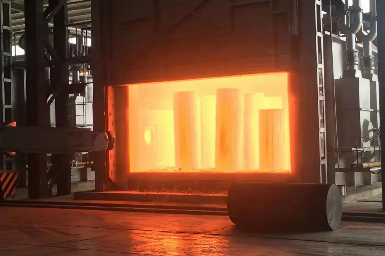
Furnace supports should carry the part at stable locations while allowing thermal expansion. A heavy flange may need multiple supports; a ring may need a level arrangement; a long housing may need distributed support; an airfoil segment may need a compatible fixture. Contact materials and surface protection must be suitable for the alloy and required cleanliness.
Fixture stiffness requires balance. A fixture that is too flexible may allow sagging, while a rigid fixture can impose new stress or prevent natural expansion. The supplier should document orientation, support points, nesting limits, and any reusable fixture revision. The first article can confirm whether the chosen support preserves critical relationships.
Load arrangement also affects thermal uniformity. Avoid mixing dissimilar part sizes, alloys, or conditions without an approved review. Define furnace working zone, spacing, monitoring, heating and cooling method, and lot identity according to the applicable process requirement.
Coordinate Stress Relief with Rough and Finish Machining
Superalloy CNC machining can release casting stress and add machining stress. Work hardening, interrupted cuts, tool pressure, and localized heat affect dimensional behavior. Use balanced stock removal where possible and alternate sides or features when the geometry benefits from it.
The blank drawing should assign stock by feature. Seal faces, bores, thin walls, bolt patterns, and datum pads can need different allowance. After rough machining, inspect the remaining envelope and datum relationship before a stress-management step. The part must retain enough stock for scale removal, movement, and final cleanup.
For a repeat program, record material removal sequence, fixture contact, tool path strategy at a useful control level, and intermediate dimensions. If the first article moves, the team can adjust the responsible operation rather than simply add stock everywhere or repeat heat treatment.
Account for Welding, EDM, and Local Thermal Inputs
Approved weld repair or assembly joining can create concentrated thermal gradients and restraint. The RFQ should define permitted locations, repair size, excavation method, joining instruction, pre- and post-join thermal steps, NDE, and dimensional recheck. The component supplier should not decide repair authority informally.
EDM introduces a recast layer and local thermal effect at the cut surface. It is not generally treated by adding an unspecified whole-part stress-relief cycle. Define recast-layer removal, surface inspection, passage cleaning, and any approved thermal step for the exact component.
Grinding, blending, peening, and straightening can also change the local condition. State which methods are permitted, where they may be used, and what inspection follows. A dimensional correction that passes immediately should still be reviewed for stability at the next manufacturing stage.
Verify Dimensional Stability with Staged Evidence
Choose characteristics that reveal movement: flatness, runout, straightness, concentricity, bore location, flange spacing, vane position, and wall relationship. Record them before and after the operation being evaluated. Use the same datum interpretation and measurement condition so the comparison is meaningful.
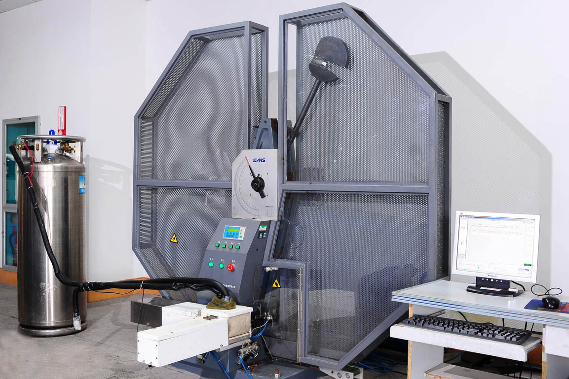
Inspection after treatment may also include visual examination, penetrant testing, hardness, metallography, or other requirement-driven checks. Material testing and analysis should confirm that the stress-management route did not conflict with the required material condition. Dimensions alone cannot establish microstructure.
Do not claim permanent stability from a single room-temperature inspection when subsequent machining, joining, or coating will add new input. The first article should pass through the complete production-intent route, with dimensional checkpoints placed where movement can be attributed to a specific step.
Disposition Movement Without Repeating Cycles Blindly
When a part moves outside the drawing requirement, identify the location, magnitude, process stage, remaining stock, and material condition. The designated authority can then review straightening, additional machining, rework, concession, or rejection. An extra stress-relief cycle should not be the automatic response.
Any reheat changes cumulative thermal exposure. Before repeating a cycle, review alloy limits, prior HIP and heat treatment, weld or coating status, coupon representativeness, and required repeat inspection. Record the disposition and link it to the affected heat and lot.
For production changes, define notification triggers for casting layout, gate-removal method, machining sequence, fixture design, furnace source, load orientation, welding route, EDM route, and straightening method. Dimensional stability depends on the whole chain.
Stress-Relief RFQ Checklist
Provide the drawing and model, exact alloy and crystal form, casting condition, prior HIP and heat treatment, repair history, quantity, critical datums, starting dimensions, machining-stock map, proposed stress source, allowed technique, route hold point, furnace or fixture requirements, staged inspection, material verification, and first-article approval points.
Request separate pricing for fixture development, intermediate measurements, approved thermal or mechanical treatment, repeat surface examination, material tests, records, and any rework review. This lets procurement compare a controlled stability plan rather than a generic furnace service.
Packaging and storage can reintroduce distortion after acceptance. Define lifting points, support spacing, stacking limits, orientation, and protection for thin walls or long spans. A casting verified flat on the inspection table can arrive bowed if it is suspended from one end or clamped against an uneven pallet. Incoming inspection at the next supplier should confirm identification, support condition, and selected stability characteristics before new machining begins.
Related FAQs
How Long Does a Typical Stress-Relief Heat-Treatment Cycle Typically Take?
Why Is Stress Relief Crucial for Superalloy Castings in High-Performance Applications?
What Are the Primary Techniques Used in Stress Relief for Superalloys?
Stress Relief in Superalloy Castings: Impact on Dimensional Stability and Fatigue Life
How Does Stress Relief Contribute to the Extended Lifespan of Superalloy Components?
Challenges in Stress Relieving Superalloys: Temperature Control, Distortion, and Microstructure