Dimensional Stability Through HIP: Precision That Lasts
HIP does not automatically create dimensional stability. An approved cycle can reduce eligible sealed internal porosity, but the same pressure-temperature exposure can release residual stress, permit creep under self-weight, move thin features, change roundness, or create local dimensional change where pores close. Buyers should treat geometry as a measured HIP output.
A dimensional HIP RFQ needs the pre-HIP casting condition, datum structure, feature-specific stock, support orientation, measurement method, follow-up heat treatment, and post-HIP acceptance. “Precision that lasts” should mean a production route with controlled evidence, not an unconditional dimensional or permanence claim.
Identify Every Mechanism That Can Move the Casting
Casting residual stress begins with nonuniform solidification and cooling. Gate removal, straightening, blasting, weld repair, rough machining, and EDM can add or release stress before HIP. During the HIP and heat-treatment cycles, the part can relax toward a different free-state shape.
Self-weight and fixture contact matter at elevated temperature. A long housing can bow between supports, a ring can lose roundness, a flange can dish, and a thin vane segment can move at mounting features. Support points should reflect the actual load path without clamping the part so rigidly that thermal expansion creates new stress.
Pore closure can produce local volume change. The effect may be too small to control some features but relevant near a thin wall, seal land, bore, or tight machining envelope. The drawing should identify critical zones and remaining stock instead of relying on one general casting tolerance.
Freeze the Pre-HIP Geometry and Material Condition
Record exact alloy, crystal structure, casting route, heat and lot, prior heat treatment, repair, cleanup, and machining. Rough machining can expose pores to the surface and alter residual-stress balance. The HIP supplier should receive a controlled incoming-condition drawing and part identity.
Measure features that can reveal movement: flatness, runout, straightness, concentricity, bore position, flange spacing, wall thickness, blade or vane profile, bolt-pattern relationship, and datum targets. Use the same datum interpretation and support condition planned for post-HIP comparison.
Pre-HIP NDE should locate major eligible pore zones and reject unsuitable cracks, inclusions, open porosity, blocked passages, or low-stock geometry. A part already below its minimum envelope cannot be restored by HIP.
Use a Feature-Specific Machining Allowance Map
Feature | HIP-related dimensional risk | Allowance or control |
Seal face or flange | Dishing, flatness change, scale cleanup | Face stock, support plan, pre/post flatness |
Long bore or centerline | Bow, runout, concentricity shift | Datum pads, bore stock, staged alignment |
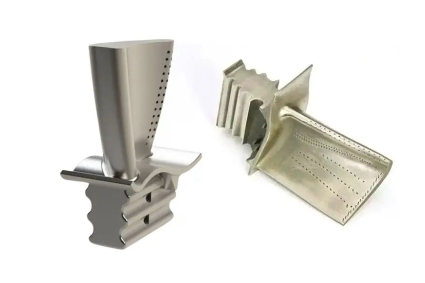
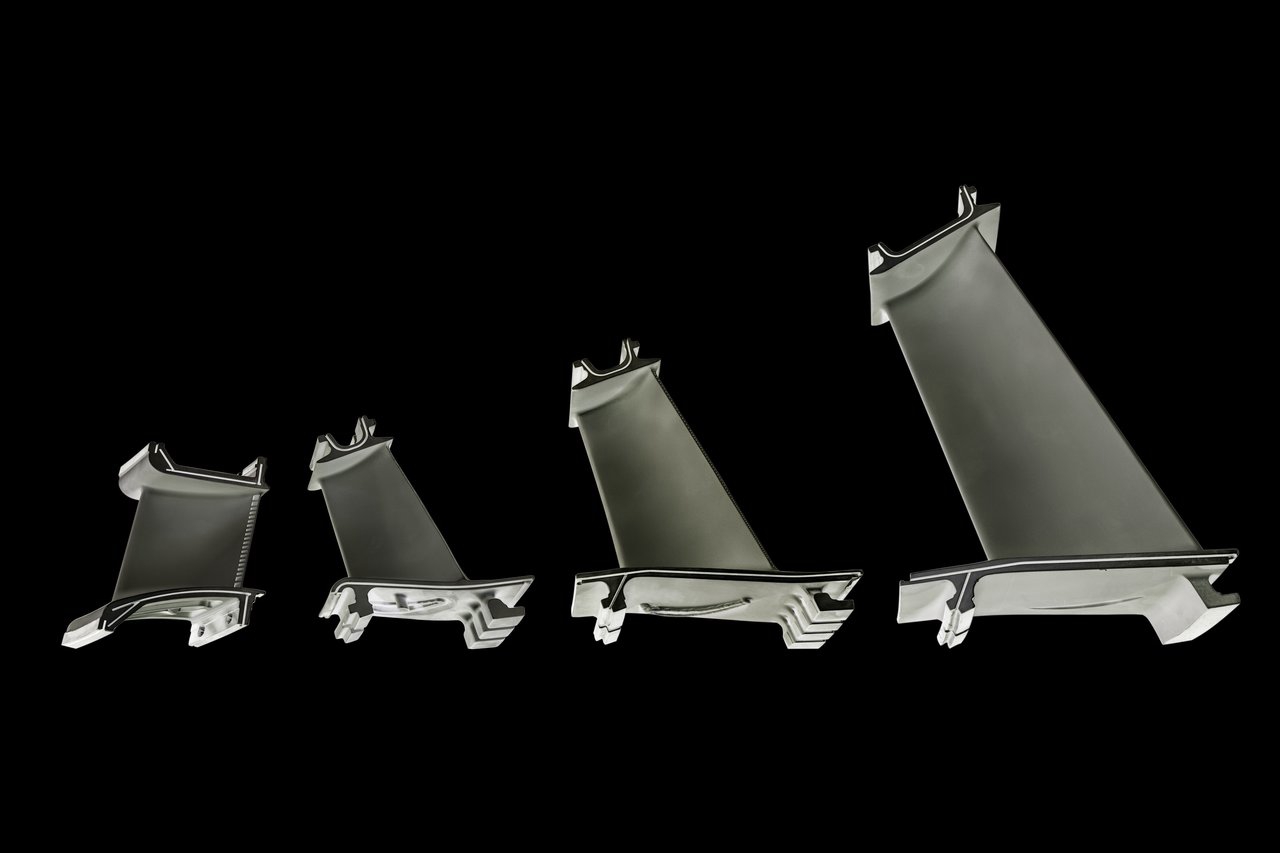
Thin wall or airfoil | Sag, local pore-collapse movement | Support contact map, profile scan, wall inspection |
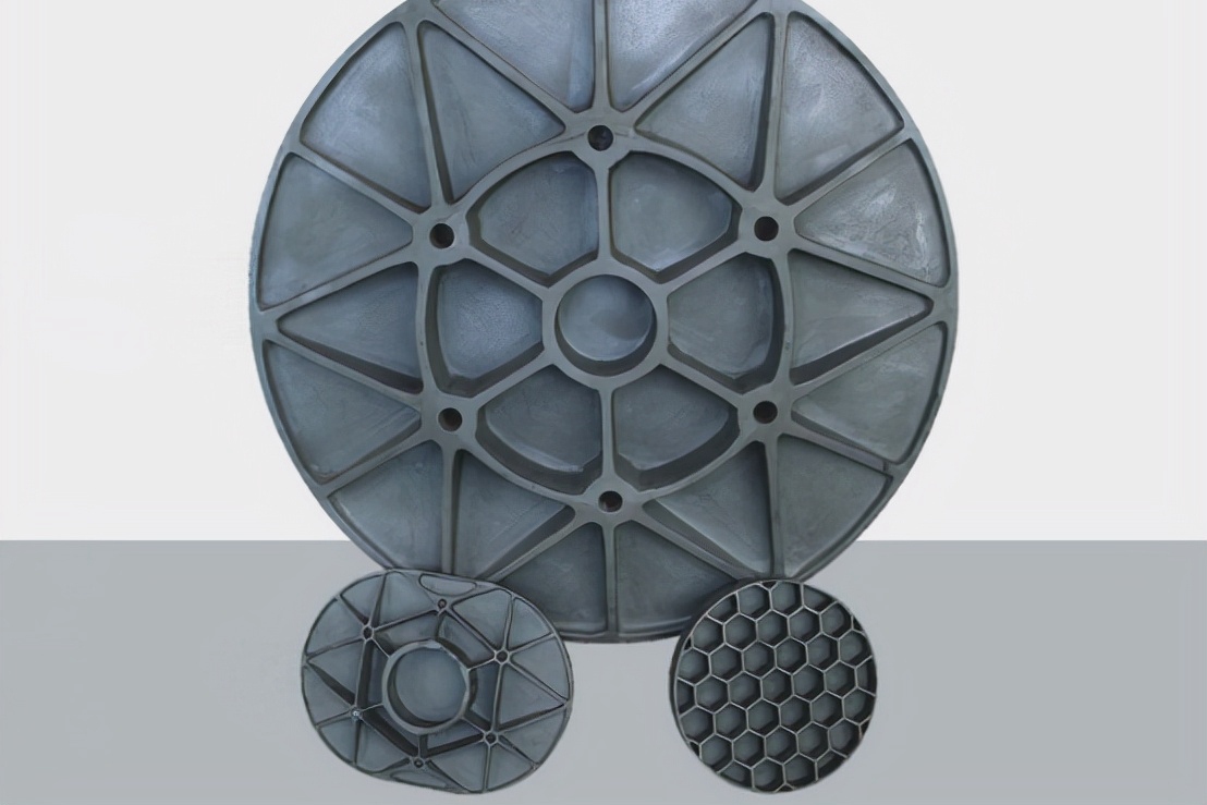
Ring or circular case | Ovality and diameter change | Roundness checks, balanced support, radial stock |
Cooling or process passage | Wall movement or restriction | CT/borescope/flow check, protected openings |
Weld preparation | Thermal movement and later joining stock | Protected end, post-HIP machining and NDE |
A blanket stock value wastes machining time while leaving one vulnerable feature unprotected. Casting and machining suppliers should agree on the min/max envelope before HIP. Identify sacrificial pads, chucking features, and locations where stock cannot be added because the surface remains as cast.
Keep enough material for HIP, follow-up heat treatment, scale or surface cleanup, and final datum establishment. If rough machining is needed for NDE access, define which surfaces are cut and which remain sealed.
Control Load Orientation and Support
The load drawing should show part orientation, fixture, support points, spacing, nesting, witness samples, and maximum quantity. Fixtures need compatible material and sufficient stability while allowing thermal expansion. Contact areas should avoid critical machined or coating surfaces.
Physical vessel capacity is not enough. Confirm controlled working zone, cycle capability, load mass, and cooling arrangement for the actual part family. Large and thin castings should not share an assumed support plan merely because they use the same alloy.
Use a production-intent load for first article. A single part supported carefully by hand may not represent a full production load with different spacing and thermal mass. Define which load changes require dimensional revalidation.
Place Rough and Finish Machining around HIP
Rough machining before HIP can reduce section, improve NDE access, and establish datums, but it can also open porosity and release stress. Review pore connectivity and leave stock for movement. Do not remove coupon, support, or identification features prematurely.
Finish machining normally uses the final approved HIP and heat-treatment condition unless the controlled route states otherwise. Superalloy work hardening, interrupted cuts, and residual stress can add later movement, so HIP is not the last dimensional risk.
Use staged machining where geometry is sensitive: rough critical surfaces, inspect, apply the approved thermal route, re-establish datums, and finish. The RFQ should state which supplier owns each dimensional checkpoint.
Sequence HIP with Heat Treatment and Repair
Follow-up heat treatment establishes material condition and adds another opportunity for distortion. The dimensional plan should cover the complete thermal sequence, not stop after the vessel cycle.
Approved weld repair can introduce local thermal stress and may occur before or after HIP according to the qualified route. Define repair limits, joining instructions, heat-treatment relationship, NDE, and dimensions. HIP does not authorize repair or guarantee that repair distortion disappears.
Straightening requires designated approval, a controlled stage, support method, dimensional target, and repeat surface inspection. A part forced into a CMM fixture should not be reported as dimensionally stable in free state.
Use Comparable Pre- and Post-HIP Metrology
Comparison requires the same drawing revision, datum scheme, support condition, measurement temperature, and method. CMM, laser scanning, structured light, gauges, CT, and manual instruments have different access and uncertainty. Select the method by characteristic.
Surface scale, roughness, probe access, and flexible walls can change the reading. State whether measurements apply to as-cast, cleaned, rough-machined, or finished surfaces. If a flexible feature is inspected in a fixture, define restraint and contact force.
Report individual characteristic movement, not only an overall “within tolerance” result. First-article data should show which features consistently move and support refinement of stock or fixtures without inventing a guaranteed shift correction.
Verify Passages and Hidden Walls
CT can compare internal geometry when part size, alloy density, resolution, and artifacts permit it. Borescope and flow checks may support accessible passages, while ultrasonic or radiographic methods address different volumetric questions. Agree coverage and acceptance before HIP.
Pore closure near a passage wall or thin section can change local thickness. Confirm critical wall and minimum opening after the complete thermal route. HIP does not remove ceramic residue or reopen a blocked core passage.
When final machining intersects a residual pore, the surface indication requires final-surface disposition. A pre-machining post-HIP scan does not automatically accept a pore opened by later cutting.
Use First Article to Establish Repeatable Movement
The first article should connect pre-HIP dimensions and NDE, load support, HIP record, follow-up heat treatment, post-HIP dimensions, passage evidence, rough and finish machining, repair, and final inspection. Review the full route before releasing production tooling or stock.
Define change-notification triggers for casting layout, gate removal, rough machining, HIP supplier or cycle, fixture, load quantity, heat treatment, straightening, metrology method, and machine setup. Repeat lots should remain comparable with the accepted geometry data.
When a feature moves out of requirement, locate the cause and check remaining stock. Use designated disposition for rework, straightening, additional machining, concession, or rejection. Do not repeat HIP or heat treatment blindly.
Preserve Geometry during Cooling, Handling, and Shipping
Dimensional control continues after the vessel reaches pressure and temperature. Cooling rate, gas flow, fixture removal, and the temperature at which a part is handled can affect flexible castings. Define when supports may be removed and how hot parts are transferred without loading a thin wall, flange, or long span.
Packaging should maintain the accepted free-state geometry rather than force the part to match a crate. Use approved lifting points, support spacing, blocking, and contact protection. Rings should not hang from one point, long casings should not bridge unsupported gaps, and machined seal faces should not carry stack load. Preserve passage caps and cleanliness without creating trapped moisture.
At the receiving machine shop, verify identity, visible damage, support condition, and selected datum characteristics before cutting. If shipment or storage changed the shape, record it before machining so the team does not attribute all movement to HIP. Handoff records should state the delivered thermal condition, remaining stock, and approved limits on additional heat or straightening.
Dimensional HIP RFQ Checklist
Send the drawing and model, alloy and casting structure, incoming condition, pre-HIP NDE, critical datums and dimensions, free or restrained measurement condition, feature allowance map, HIP cycle, load orientation and supports, follow-up heat treatment, passage checks, machining sequence, metrology plan, records, and first-article hold points.
Request separate pricing for fixture design, baseline metrology, HIP, heat treatment, repeat dimensions, CT or passage checks, rough and finish machining, straightening review, reports, and packaging. This makes dimensional risk visible without promising permanent precision.
Related FAQs
Does Hot Isostatic Pressing (HIP) Change Casting Dimensions? A Detailed Explanation
Stress Relief in Superalloy Castings: Impact on Dimensional Stability and Fatigue Life
Challenges in Stress Relieving Superalloys: Temperature Control, Distortion, and Microstructure
How Do Foundries Control Dimensional Repeatability on Complex Turbine Components?
Is Hot Isostatic Pressing (HIP) Suitable for All Superalloys? Key Limitations and Criteria