Boosting Alloy Strength with Post-Processing Techniques
“Boost alloy strength” is not a complete RFQ requirement. Tensile strength, yield strength, creep resistance, stress-rupture response, low-cycle fatigue, high-cycle fatigue, impact behavior, hardness, oxidation resistance, and surface durability are different engineering outcomes. A process that helps one outcome can leave another unchanged or create a new dimensional, metallurgical, or surface risk.
For this RFQ, buyers should define the governing load, temperature, environment, part geometry, alloy, casting structure, incoming condition, and acceptance evidence before selecting post-processing. HIP, heat treatment, machining, peening, welding, and coatings are not interchangeable “strengthening” steps. Each changes a specific part of the defect, microstructure, stress, surface, or environmental-control problem.

Translate “Strength” into a Measurable Requirement
Start with the component duty cycle. Record steady and peak temperature, dwell time, thermal gradients, rotational or pressure load, vibration, contact stress, start-stop frequency, atmosphere, and expected inspection interval. A hot-section casting controlled by creep needs a different route and test basis from a room-temperature bracket controlled by high-cycle fatigue or a valve component exposed to corrosion and pressure cycling.
Identify where failure is expected to initiate. Internal pores, inclusions, coarse or misoriented grains, a weak heat-affected zone, rough EDM surfaces, a sharp machined transition, tensile residual stress, oxidation, and coating defects require different controls. The drawing should mark critical zones and surfaces instead of applying one undifferentiated property statement to the entire part.
State the required delivery condition and property source. If the values come from a material specification, design allowables, legacy drawing, customer test method, or qualification program, cite the controlled document and sampling rule. Published handbook values do not automatically represent the actual casting section, crystal orientation, heat treatment, surface condition, or manufacturing lot.
Freeze the Incoming Part Condition
Post-process quotation depends on what arrives at each supplier. Define exact alloy, equiaxed, directionally solidified, or single-crystal structure, casting lot, gate-removal state, residual ceramic, prior heat exposure, rough-machining status, weld repair, straightening, surface contamination, and remaining stock. A process plan built for an as-cast blank may be unsuitable after critical surfaces or pores have been opened.
Use baseline NDE and dimensional inspection to prevent later ambiguity. Record known porosity, surface indications, wall thickness, datums, runout, flatness, profile, passage condition, and stock on critical interfaces. If the part is already below minimum wall or contains an ineligible crack or inclusion, later processing cannot restore missing material or erase the foreign phase.
Incoming-condition control is also essential in an outsourced route. Packaging, handling, cleaning, identification, and corrosion protection must preserve the approved state between foundry, HIP source, heat treater, machine shop, coating source, test laboratory, and final inspection.
Select the Process by the Problem It Can Actually Address
Engineering problem | Potential process contribution | Boundary that remains |
Sealed internal casting porosity | HIP may close eligible isolated pores | Open cracks, inclusions, and blocked passages remain |
Incorrect or unstable precipitate condition | Solution and aging may establish the specified microstructure | Thermal history and incipient-melting limits must be respected |
Tensile residual stress at an accessible surface | Controlled peening may introduce compressive surface stress | Coverage, intensity, masking, and surface condition require control |
Hot-gas oxidation or thermal exposure | A compatible coating system may reduce substrate exposure | Coating life depends on preparation, bond coat, geometry, and duty |
Damaged or missing local material | Approved welding may restore selected zones | Crack removal, filler, heat input, PWHT, and NDE are separate controls |
Geometry, stock, or interface requirement | CNC or EDM creates the required feature | Cutting can expose pores or leave damage that needs final inspection |
This matrix is a screening tool, not an instruction to apply every process. Adding unnecessary thermal cycles, surface work, or repair can increase distortion, cost, and qualification burden. The supplier should justify each operation against a stated defect mechanism or drawing requirement.
Where internal densification is required, specify HIP by approved cycle or parameter envelope, load support, incoming surface condition, and post-cycle evidence. Where microstructure is the objective, define heat treatment by alloy condition, furnace class or applicable equipment requirements, quench or cooling controls, and verification.
Control the Sequence, Not Just the Individual Operations
Process order changes the final result. Rough machining before HIP can expose pores to the pressure medium, while machining after HIP can uncover residual indications at the final surface. Heat treatment can relieve stress and move geometry; machining can then redistribute stress again. Coating cannot compensate for a substrate that is dimensionally unstable, contaminated, cracked, or outside the approved microstructure.
Create a route traveler with the condition entering and leaving every operation. Include cleaning, masking, inspection hold points, temperature restrictions, machining allowance, repair decisions, and preservation. Do not let separate suppliers assume that another party will perform the intermediate inspection or restore the required material condition.
Thermal sequence requires alloy-specific review. HIP may overlap part of a solutioning objective but does not automatically replace the specified solution and aging schedule. Welding can require local or full-part preheat and post-weld treatment. Coating diffusion cycles may further expose the substrate. Accumulate the complete time-temperature history before approving the route.
Preserve Surface Integrity During Machining and Peening
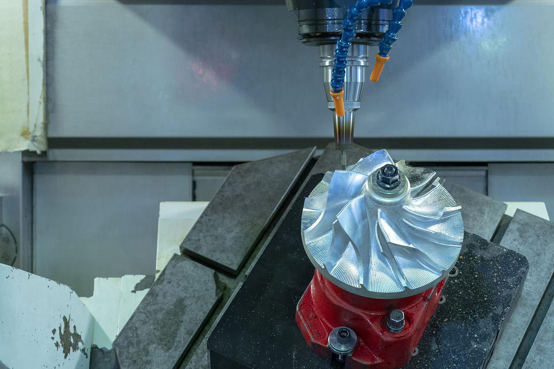
Surface-controlled fatigue performance can be lost after a sound bulk-material route. CNC machining parameters, tool condition, coolant, workholding, cut direction, and stock-removal strategy influence tearing, smearing, residual stress, burrs, and local heat. Define finish, edge condition, blend radii, and inspection on critical surfaces.
EDM is useful for hard alloys and complex passages, but recast layer, microcracking, debris, and local thermal effects require a controlled finishing and verification plan. The drawing or process specification should state whether skim cuts, polishing, etching, or recast removal are required and how the result will be checked.
Shot peening or laser peening should be tied to a qualified surface and fatigue objective. Intensity, coverage, media, contamination control, masking, access angle, edge treatment, and post-peen handling affect repeatability. Peening does not correct an internal inclusion, an undersized wall, a deep machining crack, or an unapproved weld.
Treat Coating and Welding as Engineered Sub-Routes
Thermal barrier coating changes the thermal and environmental boundary at the surface, not the nominal room-temperature strength of the substrate. Specify substrate preparation, bond coat, ceramic system, target zones, exclusions, thickness or other controlled characteristics, edge termination, cooling-hole protection, and inspection. Coating selection must remain compatible with alloy, geometry, temperature, and service exposure.
Superalloy welding needs an explicit repair map and authority. Define allowable defect removal, maximum excavation, filler, heat input, shielding, interpass control, repair count, blending, post-weld heat treatment, and NDE. Some alloys and component locations are more crack sensitive than others; a general permission to weld is not sufficient.
When coating or weld repair is outsourced, require lot and component identity through stripping, preparation, repair, thermal cycles, inspection, and reapplication. The final release package should show which surfaces were treated and which acceptance criteria were applied.
Design Inspection Around Each Claimed Outcome
Inspection should follow the claimed process contribution. Volumetric NDE can evaluate selected internal indications before and after HIP; metallography and hardness can support microstructure or thermal-condition checks; FPI can identify surface-breaking indications; dimensional inspection can detect thermal movement; surface roughness and residual-stress methods address different aspects of machined or peened surfaces.
Mechanical testing must name the property, test method, temperature, specimen source, orientation, quantity, and acceptance rule. A tensile result cannot substitute for fatigue, creep, or stress-rupture evidence. A separately cast coupon may not reproduce local solidification, grain orientation, section thickness, pore distribution, or surface history in the component.
Use material testing and analysis selectively. Chemistry, microstructure, grain assessment, density, tensile, creep, fatigue, oxidation, coating adhesion, and failure analysis answer different release questions. Agree data format, raw records, photographs, calibration references, and retention before the supplier quotes.
Assign Responsibility at Every Supplier Handoff
A multi-source route needs one controlled master sequence and a responsibility matrix. State who owns incoming inspection, process approval, transport protection, deviation review, nonconformance disposition, change notification, record compilation, and final release. Without that assignment, a part can pass each supplier's local operation while the combined route remains unverified.
Protect datums, finished surfaces, cooling passages, and identification during shipment. Packaging should support flexible geometry without forcing it into shape, avoid contact damage, and control moisture or contamination. Receiving inspection should record damage or movement before the next operation changes the evidence.
Purchase orders should flow down only the requirements relevant to each source while preserving configuration control. The final assembler or responsible supplier must reconcile records against the same part and lot rather than collecting unrelated process certificates.
Qualify the Route with First-Article and Change Control
The first article should demonstrate the full route on representative geometry and material condition. Review incoming defects and dimensions, each process record, intermediate hold points, final NDE, material evidence, surface condition, and final dimensions together. If the result fails, investigate the interaction among operations rather than adjusting the last process in isolation.
Freeze foundry source, alloy controls, casting method, rough-machining state, HIP cycle and site, heat-treatment sequence, fixtures, weld repair, machining strategy, peening parameters, coating source and cycle, and inspection method as required by the approval basis. Define which changes need notification, technical review, or repeat validation.
Production monitoring should trend measurable outputs: indication type and location, dimensional movement, repair frequency, hardness or microstructure findings, surface nonconformances, and coating defects. Trend data can expose process drift before a broad final rejection occurs.
Send an RFQ That Produces a Comparable Technical Quote
Provide the controlled drawing and model, component function, exact alloy and casting structure, governing specification, property requirements, duty conditions, critical zones, incoming state, annual and lot quantity, complete process sequence, approved or proposed subcontractors, machining stock, repair limits, NDE plan, material tests, coating or peening scope, records, first-article requirements, and change-control expectations.
Ask suppliers to separate one-time qualification, fixtures, baseline inspection, HIP, heat treatment, machining, welding, peening, coating, testing, documentation, and recurring production cost. Require assumptions and exclusions to be listed. Two quotes are comparable only when they address the same incoming condition, process boundary, evidence, and delivery state.
A credible proposal will explain which operation controls each requirement, what evidence will be supplied, and where engineering approval is still needed. That is more useful than a long list of available processes presented as universal strengthening steps.
Related FAQs
What Is the Primary Purpose of Post-Processing for Superalloy Parts?
Which Post-Processing Techniques Improve Fatigue Resistance?
How Does HIP Differ from Heat Treatment for Superalloy Benefits?
How Does Heat Treatment Impact Mechanical Properties of Superalloy Parts?
What Is Shot Peening and How Does It Boost Fatigue Resistance in Superalloys?
How Do HIP and Heat Treatment Boost CNC-Machined Superalloy Performance?