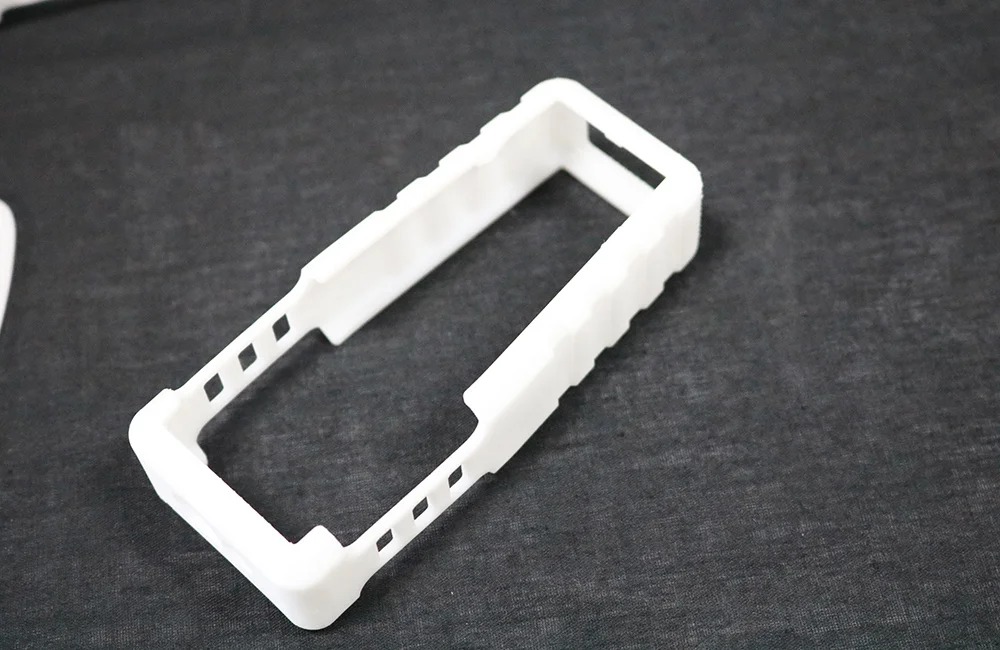
Precision Plastic 3D Printing: Resins, Thermoplastics, and Specialty Filaments
Introduction to Precision Plastic Additive Manufacturing
When dimensional accuracy, surface finish, and material performance matter, precision plastic 3D printing offers unmatched control. Whether using high-resolution resins, engineered thermoplastics, or fiber-filled filaments, the process is ideal for tooling, fixtures, and end-use components.
At Neway Aerotech, our plastic 3D printing services deliver tight-tolerance parts across industries using SLA, SLS, MJF, and high-temp FDM processes.
Plastic 3D Printing Technology Overview
Classification of Precision Printing Technologies
Technology | Tolerance (mm) | Surface Finish (Ra, μm) | Feature Resolution (mm) | Ideal Applications |
|---|---|---|---|---|
SLA | ±0.05–0.10 | 1–5 | ~0.1 | Microfluidic models, dental parts, presentation prototypes |
SLS | ±0.1–0.2 | 8–12 | ~0.4 | Functional assemblies, snap-fit housings, gears |
MJF | ±0.1–0.15 | 6–10 | ~0.3 | Structural prototypes, production enclosures |
FDM | ±0.15–0.3 | 10–20 | ~0.5 | Jigs, brackets, tooling inserts with engineering plastics |
Note: Accuracy varies based on material, orientation, and post-process method.
Selection Strategy by Printing Method
SLA: Best for achieving optical clarity and smooth surfaces for tight-fit mating parts.
SLS: Ideal for durable nylon components with functional precision and interlocking features.
MJF: Recommended for batch-consistent parts with dimensional repeatability.
FDM: Suitable for mechanically strong prototypes using reinforced and specialty filaments.
Material Options for Precision
Comparison of Resins, Thermoplastics, and Composite Filaments
Material | Tensile Strength (MPa) | HDT (°C) | Dimensional Stability | Specialty Feature | Applications |
|---|---|---|---|---|---|
SLA Engineering Resin | ~50 | ~55 | Very high | Smooth finish, biocompatible grades available | Dental, fit models, assembly tools |
Nylon PA12 (SLS/MJF) | ~50 | ~180 | Excellent | Tough, abrasion resistant | Enclosures, clips, wear-resistant housings |
Carbon Fiber PETG | ~75 | ~90 | High | Lightweight, low-warping | Brackets, drone mounts, robotics end effectors |
ABS (FDM) | ~45 | ~96 | Moderate | Machinable, ESD-safe options | Functional prototyping, housings, tooling |
TPU | ~30 | ~60 | Good | Highly flexible, >300% elongation | Gaskets, seals, impact-damping elements |
Material Selection Strategy
SLA Resin: Selected when detail accuracy and a polished aesthetic are essential.
Nylon PA12: Used for robust mechanical parts requiring minimal post-processing and tight fit tolerance.
Carbon Fiber PETG: Ideal when parts require dimensional strength and light weight without thermal deformation.
ABS: Best for production jigs, fit prototypes, or ESD-sensitive applications.
TPU: Applied where dynamic flexibility and tear resistance are critical.
Case Study: SLA and Carbon-Fiber PETG for Sensor Module Development
Project Background
An aerospace R&D team required enclosures and calibration jigs for a sensor array used in an avionics interface unit. Tight dimensional tolerances were required for the sensor mounting and connector alignment.
Manufacturing Work Flow
Material Use: SLA resin for housing fit models; carbon fiber PETG for robust jigs.
CAD Validation: Model tolerance adjusted to account for ±0.05 mm shrinkage during SLA curing.
SLA Print Setup: Parts oriented for minimal support contact; 50 μm layer thickness for smooth internal surfaces.
FDM Print for PETG: Printed with hardened 0.6 mm nozzle; enclosure rigidity verified pre-assembly.
Post-Processing: SLA surfaces polished; PETG jigs chamfered and reamed for wiring harness pass-through.
Post Process
Finishing: SLA parts polished to Ra < 4 μm; PETG parts lightly sanded and sealed.
Fit Testing: Verified with sensor placement, achieving <0.1 mm variation between iterations.
Dimensional Accuracy: 3D scanning confirmed consistency across 10 SLA and 10 FDM components.
Results and Verification
All parts met geometric and mechanical specs, enabling plug-and-play sensor installation without additional adjustment.
Dimensional deviations were held within ±0.07 mm across the batch, including complex cavity geometries and thin walls.
Polished SLA surfaces facilitated seamless light transmission and enclosure alignment with clear cover prototypes.
Lead time from design freeze to final functional assembly was 4 business days including all post-processing steps.
FAQs
Which plastic 3D printing process gives the best surface finish and detail accuracy?
Can SLA or MJF parts be used in final product assemblies?
What is the tightest achievable tolerance in plastic 3D printed parts?
Are there anti-static or flame-retardant filament options?
What post-processing options do you offer for resin and thermoplastic parts?

