Why Superalloy Welding is Key for Aerospace and Energy Components
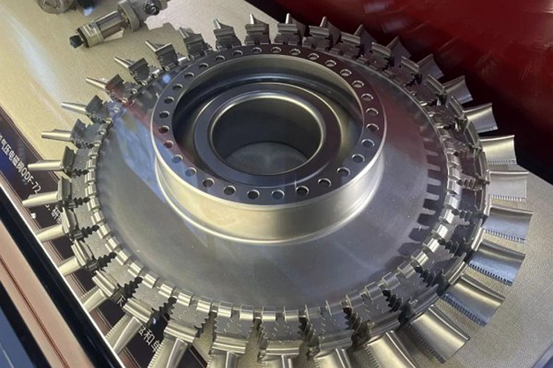
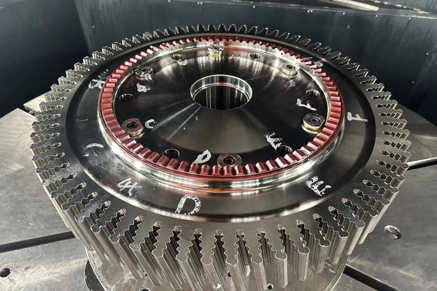
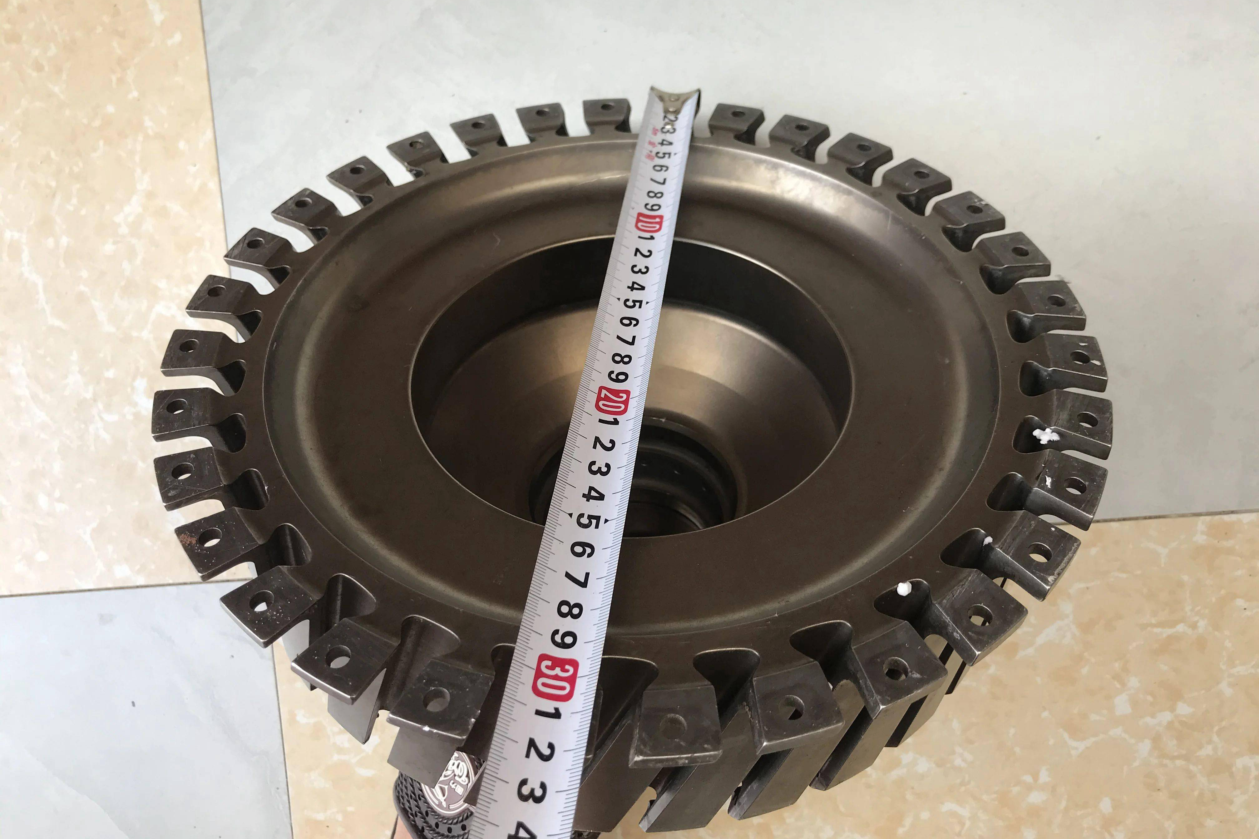
Superalloy welding is important to both aerospace and energy manufacturing, but the same weld route should not be copied from one component class to another. Thin rotating or flow-path parts, static hot-section hardware, combustor structures, turbine casings, heat-exchanger sections, valves, and process equipment experience different stress, temperature, access, inspection, and maintenance conditions.
For this RFQ, buyers should define the component class, exact alloy and product form, joint or repair location, load spectrum, temperature cycle, environment, configuration authority, manufacturing state, access, required records, and acceptance basis. The sector label alone does not choose filler, welding process, PWHT, NDE, or qualification.
Classify the Component Before Selecting the Weld Route
Component class | Dominant RFQ concern | Welding implication |
Thin sheet or combustor structure | Distortion, burn-through, thermal fatigue, edge geometry | Low and controlled heat input, fixtures, leak or contour checks |
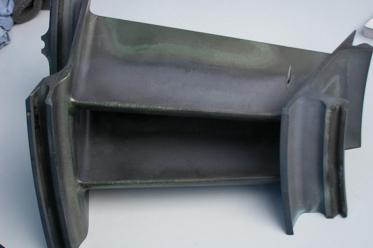
Blade, vane, or flow-path feature | Profile, wall, grain structure, coating, local stress | Restricted repair map, precision blend, orientation and coating review |
Rotating attachment or shaft feature | Cyclic load, balance, runout, surface initiation | Joint-location approval, distortion control, fatigue-relevant evidence |
Casing, ring, or duct | Large geometry, restraint, flange relationships | Sequence, support, free-state metrology and finish stock |
Valve, heat exchanger, or process part | Pressure, corrosion, thermal cycling, access | Material compatibility, leak/NDE, environment and weld-root control |
Service-exposed repair | Unknown damage, wall loss, prior cycles and coating | Incoming gate, engineering disposition and strict restoration limit |
Mark the weld zone and its functional relationship on the drawing. A joint near a seal, cooling passage, highly stressed fillet, thin wall, pressure boundary, or coating termination can need a different route from a noncritical attachment on the same assembly.
Classify new assembly, casting repair, build-up, tube attachment, crack repair, and refurbishment separately. Procedure coverage, allowed filler, excavation, heat input, and evidence should follow the operation actually being performed.
Distinguish Short-Cycle Fatigue from Long-Dwell Creep
Many aerospace and cyclic turbine components see repeated starts, stops, vibration, and strong thermal gradients. Weld toe geometry, root mismatch, local surface condition, tensile residual stress, and coating transitions can influence fatigue initiation. The qualification plan should represent the final machined or blended surface and relevant cycle.
Stationary energy components may see long dwell at temperature, pressure, thermal cycling, corrosion, or creep. Weld metal, HAZ, and dissimilar-alloy transitions can respond differently from parent material over time. Room-temperature tensile evidence alone is not enough where creep, stress rupture, or environment governs.
State operating temperature range, dwell, ramp, load direction, vibration, pressure, medium, atmosphere, and inspection interval. Select joint design and test evidence from the mechanism rather than the industry name.
Set Aerospace Part Boundaries for Geometry and Configuration
Weight-sensitive and thin-wall parts can have limited stock for correction. Welding heat can move airfoil profiles, platforms, flanges, tubes, cooling passages, and mounting datums. Define free-state geometry, wall, allowed blend, repair zone, fixture support, and post-weld measurement before work begins.
Configuration control should identify drawing and model revision, part or serial identity where required, alloy heat, casting or product form, prior heat treatment, approved repair instruction, and all subsequent thermal operations. A physical sample is not a substitute for controlled design data.
Where single-crystal or directionally solidified castings are involved, confirm whether welding is permitted at the proposed location and how the local grain, HAZ, recrystallization, and property change will be evaluated. A successful bead does not preserve the original crystal architecture.
Set Energy Equipment Boundaries for Pressure and Environment
Energy and process equipment joints can be larger, thicker, and more restrained. Fit-up, root access, penetration, interpass control, cumulative heat, PWHT, and distortion can drive the route. Define pressure boundary, leak path, corrosion side, hot side, and surfaces accessible after assembly.
Material selection should account for the actual environment, not only maximum temperature. Oxidation, hot corrosion, carburization, sulfidation, chloride or chemical exposure, and dissimilar-metal contact can make filler dilution or HAZ condition significant. The buyer should provide the governing material and corrosion basis.
For outage repairs, identify removal, cleaning, decontamination, wall mapping, crack extent, service history, prior welds, and installation constraints. The supplier should separate repairability assessment from production welding and state stop conditions.
Choose Filler for the Specific Base Material and Duty
Alloy family names are insufficient. Inconel 625, 718, 617, Hastelloy X or C-276, Rene grades, Nimonic grades, and cobalt alloys have different strengthening systems, weldability, filler choices, heat-treatment response, and environmental behavior. Confirm exact specification and condition.
Matching filler may support chemistry continuity but can increase cracking risk or require a demanding thermal route. A more ductile filler may improve manufacturability while changing high-temperature strength or environmental response. The design or repair authority should approve the selection and its service boundary.
Control filler classification, supplier, lot, diameter, storage, cleaning, and traceability. For dissimilar joints, evaluate dilution, phase formation, thermal expansion, galvanic or corrosion behavior, and the heat treatment tolerated by both sides.
Select the Welding Process from Access and Heat Input
GTAW, laser, electron-beam, resistance, or another approved process should match thickness, joint type, access, penetration, production volume, atmosphere, and qualification. A thin combustor seam, blade-tip repair, thick casing joint, and tube attachment do not share one best method.
GTAW offers flexible filler and local access but needs control of cumulative heat, shielding, operator or automation, and interpass condition. Focused-beam methods can narrow the heat footprint but require tighter fit-up, line of sight, focus, or vacuum conditions. Compare complete route and evidence.
The procedure should define preparation, gap, mismatch, shielding or vacuum, parameters, filler, sequence, preheat where approved, interpass, maximum repair cycles, cleaning, and start-stop treatment. Production geometry must stay inside qualified limits.
Design Fixtures for Thin Parts and Large Assemblies Differently
Thin aerospace structures can buckle, pull, or burn through under local heat. Fixtures should control gap and alignment while allowing thermal expansion. Heat sinks, tack sequence, support, and release timing need qualification; excessive restraint can raise cracking stress.
Large energy casings, rings, and ducts can distort under weld shrinkage and self-weight. Establish support points, assembly datum, weld sequence, pre/post measurements, and stock for final correction. Measure the part free after unclamping.
Document fixture identity and condition for repeat production. Tool wear, contact movement, heat damage, or an unrecorded clamp change can alter both penetration and geometry.
Integrate PWHT with Full Component Thermal History
PWHT may address residual stress, precipitation condition, or cracking control, but the route must fit the exact alloy, weld process, prior heat treatment, casting structure, section, coating, and later exposure.
Thin parts can distort during furnace loading and cooling, while thick restrained sections can have temperature gradients. Define furnace atmosphere or vacuum, support, loading, ramp, soak, sensor method, cooling, and deviation disposition. Review cumulative HIP, brazing, coating diffusion, and prior repair cycles.
Repeat required NDE and dimensional checks after heat treatment. A cycle can reveal delayed cracking or move geometry even when the as-welded part was acceptable.
Restore Machined, Flow, and Coated Features
Aerospace flow-path repairs can require profile scanning, wall measurement, cooling-hole protection, blend limits, and coating restoration. Energy equipment can require bore, flange, seal, root contour, leak, or flow checks. The final feature, not only the weld bead, must meet the controlled definition.
Use machining after thermal processing when the route permits it, with sufficient stock and re-established datums. Machining can expose lack of fusion, porosity, or cracks, so inspect the final surface.
If coatings are stripped and reapplied, define substrate acceptance, strip limit, masking, preparation, system, thickness, transition, passage protection, and evidence. Coating cannot hide an unaccepted weld or heat-affected zone.
Match Inspection Coverage to Geometry and Access
Visual inspection and FPI can address selected surface conditions. Radiography and CT may support internal volume or geometry; ultrasonic methods depend on alloy microstructure, section, and access. Leak, pressure, flow, CMM, scanning, balance, or runout checks answer component-specific questions.
Thin complex parts may require CT, borescope, flow, or sections because internal passages are inaccessible. Thick energy joints can challenge radiography or ultrasonic coverage and may need qualified techniques from multiple directions. State coverage and known blind zones.
Use material testing and analysis for defined chemistry, metallography, hardness, tensile, creep, fatigue, or environmental questions. A generic test list does not replace a component-specific acceptance plan.
Build Evidence for the Governing Application Mechanism
For fatigue-sensitive joints, define specimen location, weld toe or root condition, surface finish, residual-stress state, load ratio, waveform, frequency, temperature, and runout. For creep or stress rupture, define temperature, stress, orientation, dwell, and failure evaluation. Keep specimen maps.
Qualification should represent material, joint, thickness, process, heat input, restraint, PWHT, final surface, and worst-case production features. A flat coupon does not automatically cover a thin cooled vane or thick casing nozzle.
Keep manufacturing evidence within its scope. The supplier can report procedure and test results; design life, inspection interval, and field release require the responsible authority to combine those results with stress and operating data.
Control New Manufacture and Outage Repair as Separate Programs
New manufacture starts with controlled geometry, material, route, and first-article requirements. Outage repair starts with a used component whose damage, wall, coating, prior cycles, and configuration must be established. Do not price both from one generic procedure.
For non-OEM work, define lawful data use, design authority, configuration, reverse-engineering limits, intended application, and acceptance. A worn sample can inform interfaces and damage but is not automatically nominal geometry.
Set hold points after incoming evaluation, defect excavation, welding, PWHT, machining, coating, and final inspection. Stop when damage exceeds the approved restoration envelope or evidence cannot support disposition.
Send Two Distinct RFQ Packages
For aerospace component work, provide controlled part definition, alloy and grain structure, joint or repair map, weight and wall constraints, load and thermal cycle, configuration controls, process and source restrictions, fixtures, PWHT, profile and passage requirements, NDE, material tests, records, quantities, and first article.
For energy equipment, provide component and pressure or flow function, alloy and condition, joint map, service temperature and environment, section, access, outage milestones, prior service and repairs, fit-up, process restrictions, PWHT, machining, leak or pressure tests, NDE, documentation, and decision owners.
A credible supplier will not offer one sector-neutral weld route. It will connect the joint, alloy, service mechanism, production state, inspection access, and evidence to the actual aerospace or energy component.
Related FAQs
What Challenges Arise in Welding Superalloys for Aerospace and Energy Sectors?
How Does Post-Processing Enhance the Quality of Welded Superalloy Components?
Why Testing and Inspection Are Non-Negotiable for Welded Superalloy Components
Post-Weld HIP Benefits: Enhancing Integrity and Lifespan of Superalloy Welds
Which Welding Methods Best Suit High-Temperature Superalloy Components?