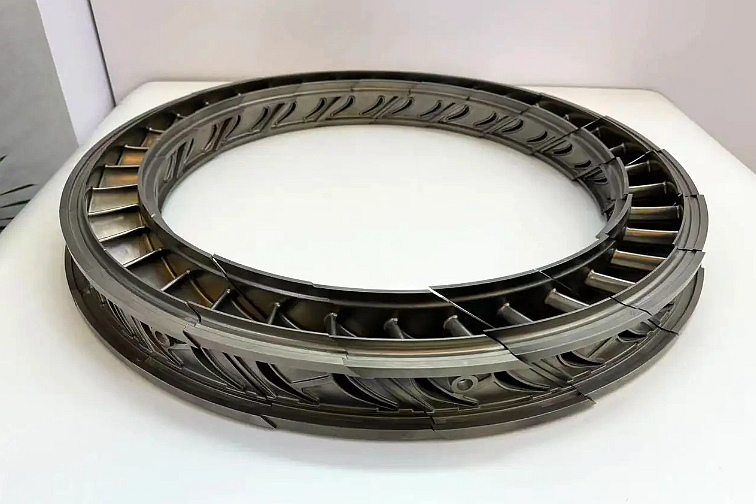
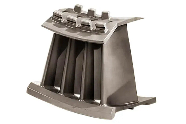
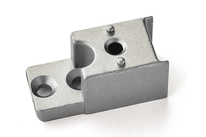
Surface Quality Matters: Post-Processing for Durability
A surface-quality RFQ should not use one roughness value for the entire casting. Seal faces, airfoils, fillets, cooling passages, bearing fits, bolt interfaces, weld zones, coating areas, and nonfunctional exterior surfaces have different damage mechanisms and inspection access. The required condition must be assigned by feature and by the final manufacturing state.
Surface processing can reduce certain fatigue initiators, prepare a coating, restore an approved repair zone, or meet a flow and sealing requirement. It cannot compensate for an undersized wall, an inclusion, an open crack, poor geometry, an incompatible alloy, or an uncontrolled service environment. Buyers should define the surface function and acceptance evidence before requesting a generic “durability finish.”
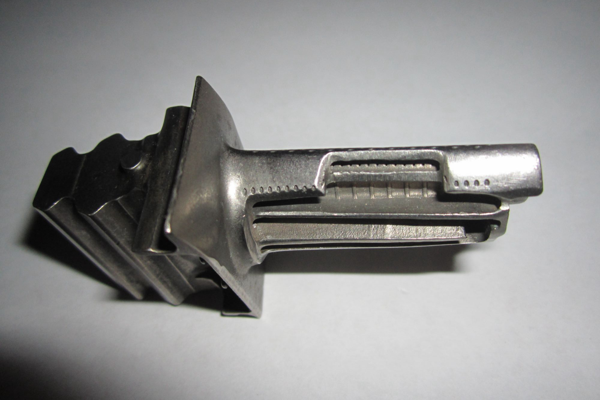
Classify Every Surface by Function and Failure Risk
Surface class | Primary engineering concern | Typical controls |
Gas-path or airfoil | Aerodynamic contour, roughness, oxidation, coating continuity | Profile, local finish, edge condition, coating-zone map |
Seal or flange face | Leak path, flatness, waviness, damage during handling | Geometry, finish direction, cleanliness, protection |
Bore or bearing interface | Fit, roundness, tearing, embedded debris | Size, form, finish, visual and dimensional checks |
Fillet or transition | Fatigue initiation, tool marks, blend discontinuity | Minimum radius, blend profile, FPI where specified |
Cooling passage | Restriction, recast, residue, inaccessible roughness | CT, borescope, flow, cleanliness or section evidence |
Coating or weld zone | Adhesion, contamination, heat-affected condition | Preparation standard, repair map, masking and final inspection |
Mark these zones on the drawing or a controlled surface map. State which surfaces remain as-cast, which are machined, ground, polished, peened, welded, stripped, or coated, and which must not be touched. A supplier cannot quote inspection coverage or masking from a general note alone.
Connect each surface class to the actual failure concern. A sealing face may be driven by waviness and flatness rather than a very low Ra. A fatigue-critical fillet may require removal of transverse tool marks and edge damage. A coating surface needs cleanliness and controlled texture that supports the approved coating system.
Convert “Smooth” into Drawing-Level Requirements
Roughness parameters describe part of a surface, not all of it. Ra can hide isolated scratches, pits, laps, tears, chatter, embedded media, burrs, recast, waviness, and unfavorable lay. Specify the parameter, limit, cutoff or filter where required, measurement direction, evaluation length, and locations. Add visual or defect criteria for conditions the numerical value does not capture.
Define edge and transition geometry explicitly. Minimum radii, break-edge limits, blend length, undercut prohibition, burr direction, and protected sharp features affect stress concentration and assembly. “Deburr all edges” can be unsafe when a metering edge, seal edge, or coating termination must retain controlled geometry.
State the inspection stage. An acceptable surface after machining may be altered by welding, peening, coating preparation, stripping, blasting, cleaning, or shipping. Release should apply to the final condition or include intermediate hold points for surfaces that become inaccessible.
Control the As-Cast Surface Before Finishing
Shell quality, slurry and stucco control, dewaxing, firing, mold handling, pour conditions, metal-mold reaction, core condition, knockout, leaching, cutoff, blasting, and handling establish the incoming surface. Grinding every indication can remove useful stock and conceal process drift. Define what may be blended and what requires NDE or disposition.
Surface-connected porosity, cracks, laps, cold shuts, inclusions, reaction layers, and core breakthrough are not ordinary roughness. The foundry should identify indication type, location, size, and root cause against the applicable acceptance basis. Cosmetic smoothing should not replace defect evaluation.
For near-net vacuum investment castings, preserve wall and profile while removing gates and approved remnants. Establish local stock and blend envelopes around platforms, bosses, fillets, and thin sections before manual finishing begins.
Protect Surface Integrity During CNC Machining
Superalloy CNC machining requires stable workholding, sharp and suitable tooling, controlled engagement, coolant delivery, chip evacuation, and a stock-removal strategy that avoids rubbing and local overheating. Tool wear can create tearing, smearing, burrs, and dimensional drift before roughness readings show a clear trend.
Specify finish direction where load, flow, sealing, or contact makes lay important. Keep tool-entry marks, dwell marks, witness steps, and blend transitions out of critical regions. For thin or flexible parts, inspect after unclamping; fixture force can temporarily improve both geometry and measured finish.
Create tool-life and in-process inspection rules for repeated parts. A first piece made with a fresh tool does not represent the end of a production run. Trend roughness, burr condition, visual defects, cutting load or other controlled indicators at the frequency required by risk.
Remove EDM Recast and Passage Damage Where Required
EDM can form complex holes and features in hard superalloys, but its thermal mechanism can leave recast, microcracks, resolidified debris, and a heat-affected layer. The permitted condition depends on feature function, alloy, process settings, and the governing specification.
Define rough and skim passes, electrode or wire controls, flushing, breakthrough strategy, recast-removal method, edge condition, and inspection. Polishing, abrasive flow, etching, or another finishing step should be qualified for the geometry; inaccessible cooling passages need evidence suited to internal surfaces.
A hole diameter or flow result alone may not reveal local recast, branching, burrs, wall breakthrough, or damaged exit edges. Combine dimensional, visual, section, CT, borescope, flow, or metallographic checks as required by the qualification plan.
Apply Peening and Polishing to Defined Zones
Shot peening and laser peening can introduce compressive residual stress at selected surfaces when intensity, coverage, media, access, masking, and initial condition are controlled. They do not repair a crack, inclusion, undersized radius, or deep machining tear. Peening over an unacceptable defect can make later visual evaluation more difficult.
Polishing and electropolishing remove or level material. The route must protect minimum wall, edge geometry, datum relationships, and surface chemistry. Define allowable removal, target zones, excluded fits or seal edges, cleaning, solution control where applicable, and final inspection. A visually bright surface is not automatically a controlled engineering surface.
Sequence peening and polishing with heat treatment, machining, welding, and coating. Later material removal can eliminate the peened layer; later heating can relax residual stress; blasting or preparation can change the measured finish. The traveler should state the accepted condition entering and leaving each operation.
Prepare Coating Surfaces Without Hiding Substrate Defects
A thermal barrier coating or other protective system depends on substrate acceptance, cleaning, surface preparation, bond coat, masking, thickness control, edge termination, and passage protection. The coating drawing should identify zones, transitions, exclusions, and permitted overspray.
Inspect substrate defects before coating makes them harder to see. Surface-breaking indications, weld boundaries, contamination, oxidation, and geometry outside the approved envelope require disposition first. Preparation texture should follow the approved coating system rather than the lowest attainable roughness.
After coating, verify the characteristics required by the specification, which may include coverage, thickness, appearance, adhesion evidence, microstructure, porosity, or passage condition. Avoid broad life claims unless the design and qualification authority has established the relevant test basis.
Keep Weld Repair Inside a Controlled Surface Boundary
Weld repair changes local geometry, microstructure, residual stress, and surface condition. The repair instruction should define approved locations, excavation, filler, heat input, preheat, interpass controls, post-weld treatment, maximum repair count, blend profile, and inspection.
The finished blend must preserve minimum wall and functional contour. On an airfoil, seal face, passage wall, or fatigue-critical transition, excess grinding can be as damaging as an unfinished weld. Use templates, scan comparison, CMM, wall measurement, or other appropriate evidence after blending.
Maintain a repair map linked to part identity. Final inspection should distinguish parent material, repaired zone, and coating or finishing applied over it. A generic certificate stating “weld repaired and polished” is not enough for configuration control.
Match Inspection Method to the Surface Question
Profilometers measure defined roughness parameters along a trace; optical instruments can map area texture; CMM or scanning evaluates geometry; FPI addresses surface-breaking indications; visual inspection detects workmanship conditions; microscopy or sections can assess recast and coating layers. No single method accepts every aspect of surface quality.
Define instrument access, sampling location, direction, calibration, resolution, filter, cleanliness, lighting, and acceptance source. Curved airfoils, small radii, deep bores, and internal passages may require replicas, witness samples, borescope, CT, flow, or destructive qualification sections.
Use material testing and analysis when metallography, coating assessment, contamination analysis, or failure investigation is required. State whether a coupon represents the component surface and how it travels through the same preparation and thermal sequence.
Preserve the Accepted Surface Through Cleaning and Shipping
Final cleaning should remove media, abrasive, chips, oils, compounds, salts, and process residues without attacking the alloy, coating, weld, or marked identity. Define cleanliness evidence for passages and wetted surfaces. Caps and plugs should not trap moisture or shed contamination.
Packaging must prevent face-to-face rubbing, point loads, coating contact, and corrosion. Protect seal faces, sharp controlled edges, bores, threads, airfoils, and coated zones with compatible materials. Use approved lifting and support points so handling does not create dents or scratches after final inspection.
Receiving inspection should record packaging condition, visible damage, protective-cap status, cleanliness, and selected critical surfaces before assembly. This separates manufacturing quality from transit or storage damage and preserves a clear disposition path.
Send a Feature-Specific Surface RFQ
Provide the controlled drawing and model, exact alloy and casting structure, surface-zone map, functional requirement by zone, incoming condition, as-cast acceptance, machining and EDM scope, roughness and lay requirements, edge and blend definitions, repair limits, peening or polishing parameters, coating specification, cleaning, inspection methods, records, quantities, and first-article plan.
Request separate pricing for casting cleanup, baseline inspection, CNC, EDM, manual blending, peening, polishing, cleaning, weld repair, coating preparation and application, final inspection, destructive qualification samples, protection, and documentation. List assumptions and inaccessible surfaces.
A technically useful quote will identify which process creates each required surface, what defects remain unacceptable, how geometry and minimum wall are protected, and which final evidence releases the part. That is the basis for a durable surface, not a universal polishing instruction.
Related FAQs
What Is Shot Peening and How Does It Boost Fatigue Resistance in Superalloys?
How Do Thermal Barrier Coatings Enhance Turbine Blade High-Temperature Durability?
Electropolishing for Aerospace: Enhancing Corrosion Resistance and Surface Integrity
How Does Surface Finish Influence Lifespan of Power Generation Equipment Parts?
Essential Surface Finishing Standards for Superalloy Components in Aerospace and Power
How Do Tests and Inspections Verify CNC Surface Quality Meets Standards?