Superalloy Containment System Accessories Processing Plant
A containment system accessory RFQ must identify the exact part and its relationship to the boundary. A penetration housing, seal carrier, support lug, connector body, instrument boss, clamp, cover, or internal bracket does not carry the same manufacturing responsibility. The supplier needs to know whether the item retains pressure, is welded to a boundary component, supports another part, or only operates inside a controlled enclosure.
The manufacturing quotation should be based on buyer-controlled drawings and approved service conditions. The component supplier can review material, casting, forging, machining, joining preparation, finishing, and inspection, but it should not infer system safety function or create acceptance criteria that belong to the responsible design authority.
Classify the Accessory and Boundary Interface
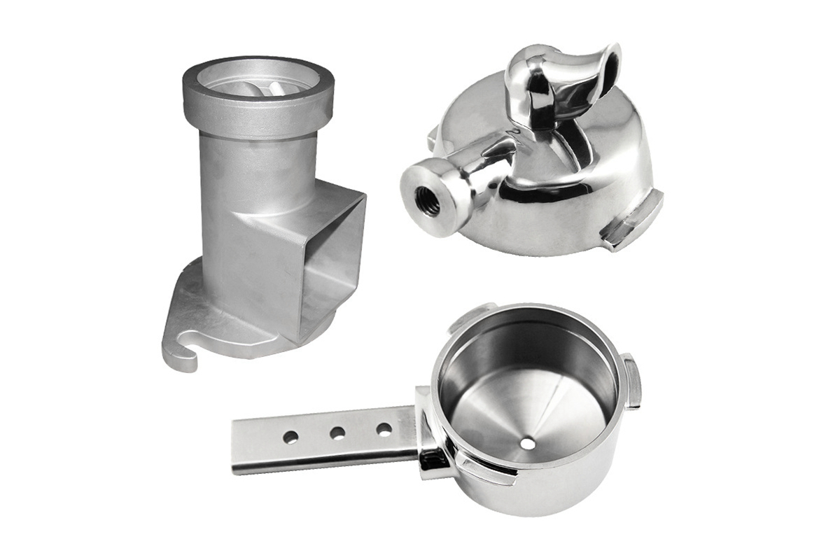
Start with a component list and responsibility matrix. Identify the part number, revision, delivery condition, mating parts, buyer-supplied items, and final assembly owner. Mark pressure-retaining walls, sealing paths, welded attachments, mechanical fasteners, instrument connections, and non-boundary supports. A model that shows neighboring equipment without interface notes can make the scope appear broader than the purchase order intends.
For each interface, state the required datum, fit, surface condition, and inspection stage. A seal carrier may be governed by concentric registers and face flatness; a penetration body may depend on weld preparation and wall thickness; a support lug may depend on pin-hole position and load-path geometry. These features should drive the route and inspection plan.
If a used accessory is supplied for replacement review, identify corrosion loss, deformation, coating residue, previous blending, and assembly damage. The sample can support interface measurement, but the buyer should define which dimensions are trusted. A worn seal face or distorted weldment should not become the nominal model.
Approve Material, Product Form, and Service Condition
Specify the exact alloy grade and purchase requirement. “Inconel” is a family name, not a material definition. Different nickel alloys can be selected for oxidation resistance, aqueous corrosion, strength, weldability, or dimensional stability. The buyer’s engineering authority should approve the grade against temperature, environment, joining route, and component function.
Product form is part of the material decision. Cast, forged, wrought, and powder-derived products can follow different specifications and test routes. Inconel alloy casting may suit an integrated penetration body when a cast form is approved. Precision forging may suit a compact high-load lug or connector. Bar machining may be lower risk for an accessible seal carrier or threaded insert.
Define heat and lot traceability, material reports, heat-treatment evidence, and any supplementary testing. If an assembly includes dissimilar alloys, identify each material at the part level and define how traceability is retained after joining. Availability should not drive an undocumented substitution.
Select the Manufacturing Route by Boundary Risk
Accessory feature | Route concern | Evidence to request |
Penetration or connector body | Wall continuity, feed zones, weld-end position | Casting or forging plan, stock map, NDE coverage |
Seal carrier or cover | Flatness, concentricity, groove and bolt-pattern relationship | Machining datum plan, CMM method, surface protection |
Support lug or clevis | Load path, hole position, grain flow or cast soundness | Approved product form, blank inspection, finish-machining sequence |
Instrument boss with passage | Deep-hole drift, intersection, burrs, cleanliness | Drilling or EDM plan, passage inspection and cleaning |
Welded subassembly | Fit-up, heat input, distortion, post-join examination | Interface drawing, responsibility matrix, sequence plan |
A route should be justified for the actual part. Complex near-net external geometry can favor vacuum investment casting. A simple heavy section may favor forging. Wrought machining can avoid tooling when quantity is low and geometry is accessible. The supplier should not present every process as equivalent or combine them without explaining each transition.
Provide prototype quantity, first-article quantity, production lot, and annual demand. Separate tooling, gauges, development samples, destructive test material, and recurring part costs. This allows procurement to compare a route that needs permanent tooling with one that uses stock and machining.
Control Casting Sections and Weld-End Stock
Cast penetration bodies and connector housings often combine a heavy flange, local bosses, and a thinner cylindrical wall. Those transitions influence metal flow, shrinkage, hot tearing, and gate placement. Mark surfaces where gates or risers are prohibited and identify radiographic or ultrasonic zones before the casting layout is approved.
The weld end requires enough stock to remove decarburized, contaminated, or geometrically unstable surface as defined by the buyer’s manufacturing plan. At the same time, excessive stock can increase cutting load and distortion. Use a feature-based allowance drawing for weld preparations, seal faces, bores, bolt patterns, and as-cast contours.
If internal passages require ceramic cores, define core prints, exit openings, minimum passage, decoring method, and residual-media verification. An internal passage needs a practical inspection method such as borescope, radiography, CT, or flow verification as specified. The supplier should identify any area that cannot be examined with the proposed technique.
Machine Sealing and Alignment Features from Stable Datums
Machining should start from a datum structure tied to the final assembly. For a penetration body, link the bore axis, flange face, bolt pattern, and weld end. For a seal carrier, link register diameter, groove position, face flatness, and fastener pattern. A local dimension that passes in isolation can still produce an unusable assembly when the datum relationship is wrong.
Superalloy CNC machining must account for work hardening, interrupted cuts, low thermal conductivity, and stress release. Rough machining a heavy flange can move a thinner body. The route may require roughing, intermediate inspection, approved stabilization, and finish machining after dimensional behavior is understood.
Deep holes and intersecting passages need tool access, chip removal, breakthrough, and burr-control instructions. Deep-hole drilling or EDM should include a method for checking drift, intersection, internal surface, recast-layer restrictions, and cleanliness. These requirements should be reviewed before the blank is released.
Define Joining Responsibility and Distortion Control
A containment accessory is often supplied weld ready rather than as a final installed item. The RFQ should name who controls joint design, filler, procedure approval, welder or equipment qualification, fit-up, preheat, interpass condition, post-join treatment, and examination. The component supplier manufactures the specified interface and should not imply authority over the completed system.
Show weld preparations, root faces, alignment lands, protected sealing surfaces, and datum targets on the controlled drawing. If a temporary strongback, fixture, or machining pad is permitted, define when it is removed and what surface inspection follows. Welding distortion should be measured against the final datum structure, not only overall length.
When machining follows joining, identify surfaces left with stock and the datums that can be re-established. When joining follows finish machining, protect seal faces and threads from heat, spatter, and handling damage. Each sequence has different inspection hold points and should appear in the quotation.
Sequence Heat Treatment, Finishing, and Cleaning
Link heat treatment to alloy, product form, and route stage. Its position relative to rough machining and joining can affect dimensions and material condition. If the assembly cannot receive a cycle applied to the blank, that restriction must be visible during material and route approval.
Define local surface requirements for seal faces, guide surfaces, weld ends, threads, and noncritical contours. A generic polishing or blasting instruction can damage a controlled edge or embed media. Any coating, hard-facing, pickling, or passivation step should include substrate preparation, masking, allowable area, and an inspection method supplied or approved by the buyer.
Cleaning instructions should address shell residue, core media, scale, penetrant, coolant, abrasive particles, and handling contamination. Blind holes and internal passages may need flushing or borescope evidence. Packaging should protect sealing surfaces and preserve identification without introducing incompatible material.
Inspect the Boundary, Leakage Path, and Interfaces
Inspection should map to risk. Dimensional inspection controls wall thickness, flange relationships, seal grooves, bores, threads, bolt patterns, and weld-end geometry. Liquid penetrant testing may address specified surface indications. Radiography or ultrasonic testing should target agreed casting or forging zones where the technique is suitable. CT may support complex internal passages when required.
Leakage or pressure testing needs a buyer-defined medium, pressure, hold condition, allowable leakage, port arrangement, component condition, and fixture responsibility. A standalone accessory test may not reproduce the final installed boundary. Distinguish blank integrity, machined-component testing, joined-subassembly testing, and final system testing.
Material testing and analysis may include chemistry, mechanical tests, hardness, metallography, or other specification-driven evidence. Each result should identify heat, lot, processing condition, and sample source. Inspection reports should reference the drawing revision and characteristic numbers.
Use First Article to Close Boundary Assumptions
The first article should demonstrate the proposed material, blank route, machining datums, weld preparations, heat treatment, surface condition, cleanliness, NDE, and leakage evidence where required. Review all interfaces before authorizing production or final installation work.
Any blending, rework, repair, or concession request should reference the exact characteristic and designated disposition authority. A correction near a seal groove or pressure wall may require repeated dimensional and surface examination. Record the change and every affected re-inspection.
After acceptance, define notification triggers for material source, tooling revision, casting layout, heat-treatment route, machining setup, joining source, surface operation, and inspection method. This keeps repeat production tied to the route demonstrated by the approved first article.
Containment Accessory RFQ Checklist
Provide the component and responsibility list, controlled drawing and model, exact alloy and product form, boundary classification, mating interfaces, approved service inputs, quantity by phase, blank or finished scope, weld preparations, machining datums, surface and cleaning requirements, NDE coverage, leakage instructions, documentation, and first-article hold points.
Request separate prices for material, tooling, development units, recurring blanks, machining, joining preparation, post-processing, inspection, test fixtures, reports, and packaging. A clear breakdown exposes responsibility gaps before purchase rather than during final assembly.
Related FAQs
Which Superalloys Are Mainly Used for Containment System Accessories?
Why Is Vacuum Investment Casting Favored for Containment System Manufacturing?
How Does Precision Forging Improve Containment System Component Performance?
What Quality Controls Are Vital for Containment System Accessory Manufacturing?
What Benefits Does Prototyping Offer in Containment System Accessory Production?