How TBC Enhances Durability and Efficiency in Alloy Components
A thermal barrier coating can change heat transfer and protect selected superalloy surfaces, but coating thickness alone does not prove component durability or efficiency. Metal temperature also depends on gas conditions, heat flux, cooling flow, geometry, contact, emissivity, coating conductivity, aging, and operating cycle. Buyers should define the performance question before selecting a test.
For this RFQ, state the component, coating system, thermal boundary, cooling configuration, desired measurable outcome, baseline condition, duty cycle, degradation mechanisms, qualification hardware, sensors, inspection, and authority for design conclusions. The coating supplier should report controlled material and test evidence without converting a coupon result into an unconditional field claim.
Define the Performance Metric Before Testing TBC
Claim to evaluate | Required measurable quantity | Common interpretation limit |
Lower substrate temperature | Metal-side temperature or validated heat-flux response | Depends on cooling, geometry, gas boundary and sensor location |
Reduced heat flow | Heat flux and temperature gradient through known geometry | Coupon conductivity may not represent a curved coated part |
Higher efficiency | System output, fuel or energy input, cooling demand and controls | Coating alone cannot isolate all system variables |
Longer coating durability | Cycles or exposure to a defined failure criterion | Test severity and specimen geometry control the result |
Improved oxidation protection | Bond-coat and oxide-scale condition after exposure | Does not automatically represent erosion or hot corrosion |
Maintained component integrity | Coating, substrate, cooling and geometry evidence | Requires design and operating assessment beyond coating inspection |
Define units, sensor or inspection method, locations, data rate, baseline, acceptance, and uncertainty. “Improved thermal performance” is not a test instruction. A buyer asking for a substrate-temperature change should supply or approve the thermal boundary that makes the measurement meaningful.
Separate material qualification, process qualification, component demonstration, and field monitoring. Each level answers a different question and has a different cost, representation, and decision owner.
Establish a Controlled Uncoated or Approved Baseline
A performance comparison needs a baseline with the same substrate alloy, geometry, surface condition, cooling, sensor placement, fixture, heat source, and test cycle. Comparing a coated component with a different uncoated part can mix coating effects with casting, machining, cooling-hole, or measurement variation.
When an uncoated part cannot be tested, use an approved prior system or modeled baseline and state the limitations. Preserve raw data, calibration, part identity, coating condition, and photographs. Do not report only the percentage change.
If the coating system replaces a prior material or process, compare bond coat, top coat, thickness, structure, preparation, thermal cycle, and aging state. A new top coat on a new substrate is not directly comparable to a service-aged legacy system.
Connect Coating Properties to a Thermal Model
Thermal conductivity, heat capacity, density, emissivity, thickness, porosity, interfaces, and contact resistance influence the coating's thermal response. Their importance changes with steady or transient exposure. The model should include substrate, bond coat, oxide scale, ceramic, cooling passages, and external boundary as required.
Use measured property data from representative material and condition where the design basis requires it. As-deposited conductivity can change through sintering, phase evolution, cracking, pore change, and deposits. State temperature, atmosphere, aging, direction, and method.
Model correlation needs a component or representative-rig measurement. Adjusting unknown properties until a curve fits is not independent validation. Record assumptions and sensitivity so the buyer can see which inputs dominate.
Measure Heat Transfer on Representative Geometry
Flat coupons are useful for controlled thermal-property tests, but curvature, thickness transition, edge, hole, bond coat, and local coating variation affect component heat flow. Use representative coupons, subcomponents, or instrumented hardware when geometry is part of the question.
Define heater or hot-gas profile, cold-side boundary, cooling flow, pressure, fixture conduction, radiation, sensor type, attachment, location, sampling, stabilization, and cycle. Surface temperature from optical methods depends on emissivity and line of sight; embedded sensors can disturb the local field.
Where heat flux is derived from temperatures, include material properties, distance, geometry, and uncertainty. Do not quote a universal temperature reduction from a single coating thickness without the boundary conditions.
Treat Cooling Flow as Part of the TBC Result
Film-cooling holes, internal passages, impingement features, slots, and exit edges interact with coating. Overspray, bond-coat buildup, ceramic thickness, preparation debris, or reopening can change area, direction, roughness, and flow. A coating can be thermally sound on a coupon while degrading a component's cooling distribution.
Define hole masking, permissible coating entry, reopening method, edge condition, cleaning, and flow acceptance. Use CT, borescope, pin or dimensional checks, and flow testing as applicable. Record results before and after coating where comparison is required.
System efficiency claims that depend on reduced cooling demand require design-controlled tests. The coating supplier should provide coating and passage evidence; the responsible authority sets operating flow and evaluates system benefit.
Define Thermal-Cycling Severity and Failure Criterion
Thermal-cycling tests vary widely in hot temperature, cold temperature, dwell, ramp, heat source, cooling method, atmosphere, specimen geometry, stress, and inspection frequency. Cycle count has no useful meaning without these conditions.
Define failure as spalled area, crack length, exposed bond coat, thickness loss, edge damage, adhesion change, or another controlled endpoint. State whether local repair, edge failure, or coupon-fixture damage counts. Use consistent imaging and inspection intervals.
Qualification should represent substrate, bond coat, ceramic, application method, thickness, edge, curvature, and thermal history. A pass on a thick flat coupon should not be extended automatically to a thin airfoil or complex shroud.
Track Oxide-Scale Growth and Interface Damage
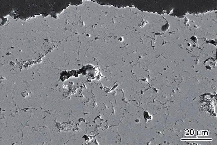
The thermally grown oxide forms between bond coat and ceramic during exposure. Composition, continuity, thickness, growth stress, rumpling, bond-coat depletion, interdiffusion, and local defects can influence spallation. Evaluation usually requires representative sections or other approved methods.
Map section locations and preserve orientation. A single section can miss local edge, hole, fillet, or shadowing problems. Combine coupon sections with component visual, thickness, and damage mapping when the qualification plan requires it.
Use comparative exposure at relevant temperature and atmosphere. Accelerated conditions can rank systems but may change the dominant mechanism; state the correlation limit.
Evaluate Erosion, Deposits, and Environmental Attack Separately
Particle erosion, foreign-object impact, molten or reactive deposits, hot corrosion, and gas chemistry can damage a coating differently from clean thermal cycling. A system with good cyclic spallation resistance may still erode rapidly or react with deposits.
Define particle material, size, velocity, angle, temperature, concentration, deposit composition, exposure, and evaluation. Laboratory erosion or corrosion tests should reproduce the intended mechanism rather than combine uncontrolled severities.
Inspect coating loss, roughness, cracks, penetration, reaction products, bond-coat condition, and substrate effects as appropriate. Do not describe a coating as universally durable from one environmental test.
Use Adhesion Tests Within Their Representation Limits
Adhesion-related tests depend on specimen geometry, adhesive or fixture, loading rate, alignment, coating thickness, surface preparation, and failure location. A measured value can be limited by the glue, ceramic cohesion, interface, bond coat, or substrate preparation.
Report where failure occurred and how much of each mode was present. A high number with fixture or adhesive failure may not quantify the coating interface. A lower value with a known cohesive mode can answer a different question.
Use adhesion tests as one part of process comparison or specification compliance. Combine them with microstructure, thickness, thermal cycling, and representative geometry evidence.
Measure Thickness and Structure by Zone
Complex parts do not receive perfectly uniform coating. Line of sight, spray or vapor angle, part motion, shadowing, masks, holes, and edges create local variation. Define critical zones and representative coupon positions in the load.
Use nondestructive thickness methods where suitable and destructive sections where layer structure must be seen. Identify total system, bond coat, ceramic, and oxide scale separately when required. State porosity, cracks, columns, splats, or phase evaluation methods and references.
Trend results by component position, coating load, feedstock lot, and equipment setup. A load average can hide a repeatable thin or dense zone on one feature.
Inspect Spallation and Damage During Service or Rig Tests
Visual maps should record crack networks, chips, exposed bond coat, edge lifting, erosion, deposits, discoloration, blocked holes, and affected area. Use consistent lighting, scale, orientation, and zone names. Photographs without component location have limited value.
After exposure, examine coating, bond coat, oxide scale, substrate, cooling passages, and geometry together. A spalled area may be driven by interface growth, impact, edge design, substrate deformation, coating thickness, or local overheating.
For refurbishment decisions, define strip limits, minimum wall, depletion, crack acceptance, prior cycles, and recoat qualification. A used coating is not automatically a direct measure of remaining service interval.
Build First-Article and Production Monitoring Around Risk
The first article should combine substrate acceptance, preparation, material lots, process records, component loading, masks, thickness maps, passage checks, coupons, sections, thermal or other qualification tests, and final inspection. Review the evidence against the original performance metric.
Production monitoring can use witness coupons, thickness, weight, visual, process parameters, material lots, or periodic sections as defined by the approved plan. A coupon should occupy a representative position and follow the same thermal and deposition route.
Set change-control triggers for substrate condition, bond coat, ceramic feedstock, supplier, application method, equipment, parameters, loading, masks, heat treatment, inspection, and coupon design. Material or process change can invalidate prior correlation.
Send a Performance-Validation TBC RFQ
Provide the controlled component definition, substrate and coating system, desired measurable outcome, baseline, thermal and cooling boundary, service cycle, environment, coating zones and features, application method, thickness and structure, sensors, models, test hardware, cycling, failure criteria, inspection, coupons, quantities, first article, records, and change control.
Ask suppliers to separate coating manufacture, representative hardware, instrumented tests, thermal-property testing, cycling, erosion or environmental tests, destructive sections, passage checks, data analysis, documentation, and recurring production monitoring. Require assumptions and uncertainty.
A credible TBC performance claim states the tested configuration, boundary conditions, measured result, failure criterion, and representation limit. Durability and efficiency cannot be reduced to a coating name or one coupon value.
Related FAQs
What Is the Main Function of TBCs in High-Temperature Alloy Applications?
How Does Plasma Spray Differ from EB-PVD in TBC Application Methods?
Key Factors Determining Thermal Barrier Coating (TBC) Effectiveness on Superalloys
How Thermal Barrier Coatings Boost Turbine Blade Performance and Lifespan
What Tests Verify the Quality and Durability of TBCs on High-Temperature Alloy Parts?