Benefits of Material Testing and Analysis on Superalloy Castings
Material testing adds value to a superalloy casting only when each test answers a defined release, qualification, or failure-analysis question. Chemistry, metallography, radiography, CT, FPI, tensile, creep, fatigue, hardness, dimensions, and coating sections are not interchangeable. A long test list can still leave the buyer's main risk unresolved.
For this RFQ, buyers should identify the component, alloy, casting structure, duty, critical zones, governing specifications, expected defect or property, specimen source, sampling, test condition, acceptance, report content, and disposition authority. The laboratory and manufacturer should explain what every method can and cannot conclude.
Begin with a Question-to-Test Matrix
Buyer question | Appropriate evidence family | What it does not prove alone |
Is the alloy chemistry correct? | OES, ICP-OES or another specified chemistry method | Grain structure, internal defects or mechanical properties |
Are surface-breaking cracks present? | FPI or another approved surface method | Sealed internal porosity or creep strength |
Are internal indications acceptable? | Radiography, CT or qualified ultrasonic method | Exact material properties or every defect orientation |
Is grain structure or phase acceptable? | Macroetch, orientation method or metallography | Whole-part internal condition |
Does the thermal route produce required properties? | Hardness and specified mechanical or microstructure tests | All service mechanisms or every component zone |
Does the part meet drawing geometry? | CMM, scanning, gauges and feature-specific methods | Material integrity outside dimensional characteristics |
Build this matrix before quotation. Link each question to component zone, manufacturing stage, method, sampling, acceptance source, record, and responsible reviewer. This prevents duplicate tests and exposes risks with no evidence plan.
State whether the test is for incoming material control, process qualification, first article, lot release, periodic monitoring, nonconformance, or failure analysis. The same method can use different sampling and acceptance for each purpose.
Verify Chemistry with the Correct Sampling Boundary
Exact alloy identity is the first boundary. Define material specification, elements and limits, melt or heat traceability, sampling location, sample preparation, method, calibration, and report format. Surface contamination, coating, weld filler, segregation, and oxidation can affect local readings.
OES can support alloy verification for suitable materials and preparation; ICP-OES or other laboratory methods can address specified elemental analysis; portable methods may support sorting under an approved plan. The governing requirement determines which result releases the material.
Keep master heat, remelt, casting heat, revert, filler, and repair material identities distinct. A compliant bulk chemistry result does not show local inclusion, segregation, coating contamination, or final microstructure.
Use Macrostructure and Metallography by Location
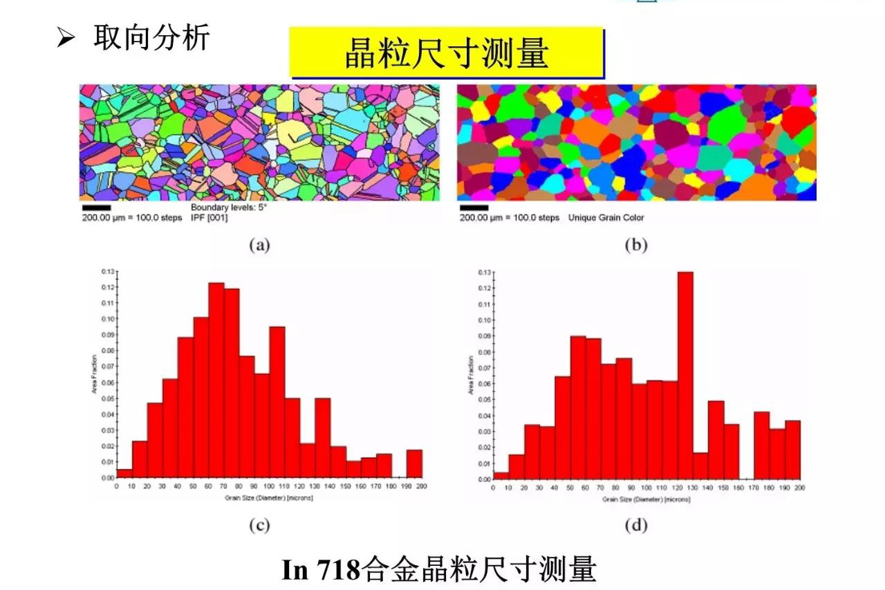
Macroetch or grain-display methods can evaluate equiaxed grain distribution, directional structure, single-crystal anomalies, weld macrostructure, and selected segregation features. Metallography can examine phases, precipitates, carbides, inclusions, pores, cracks, heat-affected zones, recast, coating layers, and oxide scale at a prepared section.
Every section is local and destructive. Mark extraction location, plane, orientation, distance from surfaces, critical feature, and specimen identity. A coupon should not represent a thick junction, thin wall, cooling passage, weld repair, or coating edge unless the plan justifies it.
Define preparation, etchant, magnification, field selection, measurement method, image retention, reference standard, and acceptance. Avoid subjective statements such as “normal microstructure” without an approved comparison.
Match NDE to Defect Type and Geometry
FPI addresses surface-breaking indications after suitable cleaning. Radiography projects density differences through the part. CT can map selected three-dimensional conditions where size, section, alloy density, resolution, and artifacts permit. Ultrasonic methods depend on surface, geometry, microstructure, frequency, orientation, and access.
Specify critical zones, full or sampled coverage, method revision, sensitivity, calibration or reference standard, surface condition, timing, operator requirements where applicable, and acceptance. State blind zones and limitations. A method name without coverage is not an inspection plan.
Inspect at the stage when the defect can be found. Check repair excavation before filler hides it, castings before expensive finishing where appropriate, post-HIP condition where required, final machined surfaces after pores can open, and coated parts before layers obscure the substrate.
Separate Tensile, Creep, Rupture, and Fatigue Questions
Tensile testing measures monotonic response under defined temperature and rate. Creep measures time-dependent deformation under sustained load and temperature. Stress rupture evaluates time to failure under specified conditions. Fatigue addresses cyclic load or strain, while thermal-mechanical fatigue couples mechanical and temperature cycles.
Define method, specimen geometry, source, orientation, surface condition, heat treatment, temperature, environment, load or strain, waveform, ratio, frequency, dwell, runout, quantity, and acceptance. Results without these conditions cannot be compared responsibly.
Select tests from component duty and specification. A room-temperature tensile pass cannot establish long-dwell creep, thermal cycling, or high-cycle fatigue. Testing every property can be costly without creating a better release decision.
Control Specimen Representation
Separately cast coupons can support chemistry and furnace control but may not reproduce component solidification, wall, grain, pore distribution, cooling, or surface. Integrally cast specimens share more of the mold route but still may not represent every critical zone. Component-extracted specimens provide direct local evidence at higher hardware cost.
Record alloy heat, casting lot, coupon type, mold or load position, heat treatment, HIP, machining, orientation, and extraction map. Ensure specimens follow the same thermal route as the represented parts. Keep deviations visible.
For DS and SX components, orientation can affect properties. For repaired or welded components, locate specimens relative to weld metal, fusion line, HAZ, and parent material. For coatings, use representative substrate, preparation, load position, and layer system.
Use Hardness as a Process Indicator, Not a Universal Property
Hardness can support heat-treatment, weld, gradient, or material-condition review. It is fast and location based, but it does not directly establish tensile ductility, creep, fatigue, fracture, oxidation, or service life.
Define method, load, surface preparation, thickness, spacing, location, number of readings, and acceptance or comparison. Curvature, thin coating, edge distance, work hardening, decarburization or surface reaction, and microstructural heterogeneity can influence the result.
Investigate unexpected hardness with chemistry, heat-treatment record, metallography, specimen condition, and mechanical data as appropriate. Do not convert a hardness correlation into a guaranteed component property without an approved basis.
Tie Dimensional Inspection to Process Stages
Casting, gate removal, straightening, HIP, heat treatment, rough machining, welding, coating, and final machining can each move geometry. Define datums and free or restrained measurement condition at the stages needed to understand the route.
CMM, scanning, gauges, optical methods, runout fixtures, flow, and wall measurements answer different geometry questions. Specify method, support, orientation, temperature, feature list, sampling, and report. A full scan does not automatically apply the drawing's datum logic.
Use first-article deltas to allocate stock, adjust tooling or fixtures, and set intermediate hold points. Final dimensions alone cannot show which process created movement.
Build a Sampling Plan from Risk and Lot Definition
Define the production lot: alloy heat, casting heat, mold run, furnace load, HIP load, machining batch, coating load, or another controlled grouping. Different characteristics may need different lot boundaries.
Sampling should consider criticality, process stability, destructive cost, defect distribution, geometry, and specification. A small random sample may miss location-specific casting defects; 100 percent inspection may still use a method insensitive to the concern.
State sample selection, frequency, escalation, reduced inspection if permitted, failed-sample treatment, affected quantity, and resampling rules. Do not invent a retest path after a failure.
Design Reports for Technical Review
A report should identify part or specimen, drawing and specification revision, lot and heat, test method revision, equipment, calibration status, preparation, location and orientation, conditions, actual results, acceptance limits, pass or fail status, deviations, reviewer, and attachments.
Include raw curves, images, scan data, maps, and fracture locations where required. A one-line certificate can be useful for summary but does not replace underlying evidence when the purchase order requests it.
Use consistent filenames, units, coordinates, zone names, and part identity. Reports from outside laboratories should reconcile with manufacturer traceability and the final shipment.
Use Failure Analysis to Find the Manufacturing or Service Cause
Failure analysis starts with preservation. Record as-received condition, fracture location, deposits, coating, wear, distortion, service history, prior repairs, and handling. Do not clean, cut, or open the part before the evidence plan is approved.
Use visual examination, NDE, fractography, sections, chemistry, microstructure, hardness, dimensions, and operating data selectively. Distinguish initiation from final overload and separate manufacturing defect, design stress, environment, operation, and maintenance hypotheses.
A sound report identifies evidence, competing explanations, confidence, and limitations. Corrective action should address the supported cause and be validated through production or test evidence.
Connect Results to Supplier and Buyer Responsibilities
The manufacturer owns process and part traceability, specimen preparation, outside-source flow-down, and release evidence within the contract. The laboratory owns method execution and reporting within its accredited or approved scope where required. The buyer or design authority owns requirement selection and engineering disposition unless assigned differently.
Define who approves procedures, witnesses tests, selects samples, accepts deviations, and reviews failures. This prevents a laboratory from being asked to make a design decision or a manufacturer from changing acceptance after results are known.
At handoffs, preserve part, specimen, orientation, condition, and chain of custody. A test result detached from its source is of limited value.
Prepare a Material Testing RFQ That Avoids Waste
Provide the controlled drawing and model, exact alloy and casting structure, process route, component duty, critical zones, governing specifications, expected defects and properties, lot definition, test matrix, specimen types and maps, methods, conditions, sampling, acceptance, witness or source requirements, report format, retention, quantities, and disposition process.
Ask suppliers to separate test-plan review, specimen hardware, extraction and machining, NDE setup, scans, destructive testing, laboratory work, failure analysis, data review, documentation, and recurring lot-release cost. Require method limitations and turnaround assumptions.
The benefit of material testing is a decision supported by traceable evidence. A credible plan uses the fewest methods that fully answer the RFQ risks, while preserving enough data to investigate variation and failure.
Related FAQs
Which Testing Methods Ensure Integrity and Reliability of Superalloy Components?
What Defects Can Material Testing Reveal in Superalloy Parts?
What Is Chemical Verification and Why Is It Essential in Superalloy Manufacturing?
What Is the Difference Between Tensile Testing and Fatigue Testing in Superalloys?
How Does NDT Ensure the Quality and Integrity of Superalloy Components?
How Does Failure Analysis Improve Superalloy Performance and Lifespan?