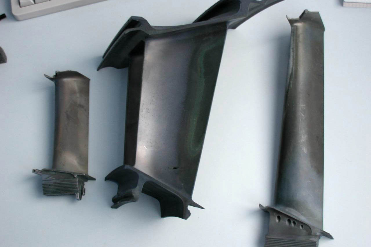
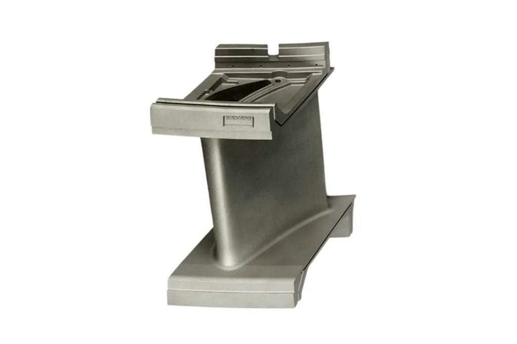
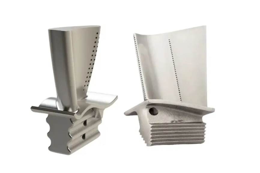
5 Benefits of Superalloy Welding on Superalloy Components Manufacturing
Superalloy welding is valuable when it solves a defined joining, build-up, or repair problem within an approved design boundary. It does not automatically improve parent-metal strength, fatigue resistance, or service life. Heat input creates a fusion zone, heat-affected zone, residual stress, distortion, and crack risk that must be addressed by alloy-specific procedure, inspection, and post-weld processing.
For this RFQ, buyers should identify exact base and filler alloys, material condition, casting or wrought structure, joint or repair location, load path, service temperature, accessibility, maximum repair envelope, required post-weld heat treatment, machining stock, NDE, and approval authority. The five benefits below apply only when those controls are established.
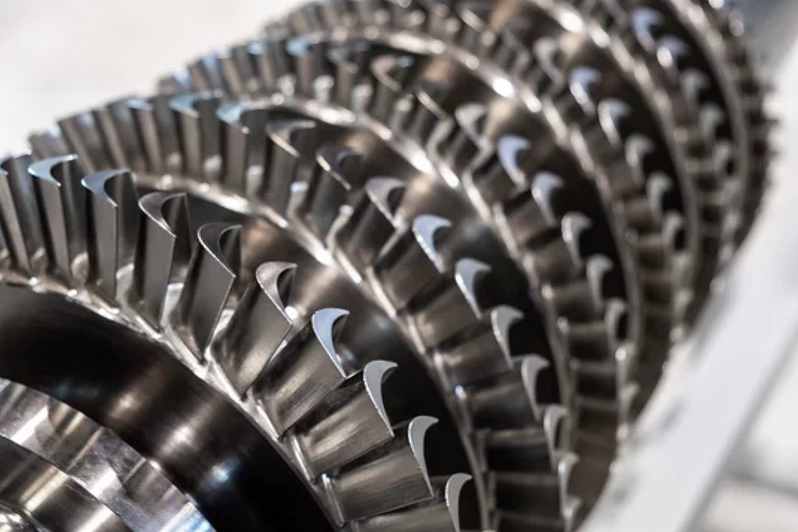
Screen Weldability Before Selecting a Process
Nickel- and cobalt-based alloys differ in solidification cracking, liquation cracking, strain-age cracking, hot-ductility behavior, gamma-prime content, carbide response, and sensitivity to prior thermal exposure. A process that works for one Inconel, Rene, Hastelloy, Nimonic, or casting grade should not be transferred to another by alloy family name.
Confirm chemistry, product form, grain structure, heat-treatment condition, section thickness, prior repairs, coating or contamination, and service exposure. Used parts can contain oxidation, depletion, embedded media, fatigue cracks, or unknown thermal history. Cleaning and FPI alone may not establish a suitable welding condition.
The supplier should review the drawing, joint stress, weld orientation, access, restraint, dilution, filler compatibility, and required properties before choosing GTAW, laser, electron-beam, resistance, or another approved method. Process selection follows the joint problem; it is not a catalog preference.
Benefit 1: Join Separately Manufacturable Sections
Welding can allow a component to be divided into cast, forged, formed, or machined sections that are easier to make and inspect before assembly. This may improve access to internal features, reduce casting complexity, or let different operations use appropriate fixtures. The design authority must approve the joint location and its effect on load, temperature, flow, and inspection.
Place joints away from highly stressed transitions, inaccessible cavities, sealing interfaces, and severe thermal gradients where possible. Define root configuration, fit-up, gap, alignment, land, backing or purge, tack sequence, and permissible mismatch. A joint that is easy to reach but difficult to inspect or finish can shift rather than reduce manufacturing risk.
Provide part-level datums and assembly dimensions. Weld shrinkage and restraint can move flanges, bores, passages, and thin walls. The route should preserve finish stock, use a planned sequence, and measure geometry after release from tooling.
Benefit 2: Restore Approved Local Casting Defects
An authorized weld repair can replace material removed during excavation of a local surface defect, which may avoid rejecting an otherwise usable casting. The benefit applies only where the drawing or purchase specification permits repair and defines location, size, depth, frequency, and required authorization.
Map the original indication, removal boundary, remaining wall, repair layers, blend, and final inspection. Grinding until an indication disappears without recording depth can violate the repair envelope. Internal inclusions, broad porosity, through-wall cracks, or defects in prohibited zones may require rejection rather than repeated excavation.
Control filler, heat input, shielding, interpass temperature, bead placement, cleaning, and maximum repair cycles. The repaired zone and heat-affected material need inspection and, where specified, metallurgical or property evidence. “Weld repaired” is not a complete release statement.
Benefit 3: Add Controlled Local Stock for Final Machining
Weld build-up can provide controlled material for an approved dimensional recovery, seal land, flange edge, or machining feature when the engineering definition permits it. This can be useful when a local area lacks finish stock but the surrounding geometry and wall remain acceptable.
The repair plan should define preparation, maximum build-up, fusion boundary, filler, final contour, minimum parent wall, machining datum, and inspection. Material addition cannot correct an incorrect load path, distorted base geometry, or widespread undersize. Evaluate the full geometric envelope before repair.
Leave sufficient build-up for final machining without excessive heat accumulation. After cutting, inspect the finished surface because machining can expose lack of fusion, porosity, or cracking that was not open before.
Benefit 4: Integrate Inserts, Tubes, and Functional Features
Welding can attach compatible inserts, tubes, brackets, bosses, or other features that are impractical to cast or machine as one piece. This supports modular manufacturing when the joint is accessible, inspectable, and compatible with service temperature, vibration, pressure, and thermal expansion.
Control fit-up and identity of every mating item. Small tubes and thin inserts are sensitive to burn-through, blockage, distortion, and purge quality. Define penetration, internal contour, mismatch, cleanliness, and flow or leak checks as applicable. Protect passages from filler intrusion and debris.
Dissimilar-alloy joints require particular review of dilution, thermal expansion, phase formation, galvanic or environmental behavior, and post-weld cycle compatibility. A filler that deposits successfully may not satisfy the required service or heat-treatment condition.
Benefit 5: Support Controlled Refurbishment Decisions
For service-exposed components, welding may be one step in an approved refurbishment route after stripping, cleaning, dimensional review, NDE, and engineering disposition. It can address selected local damage; it does not reset accumulated creep, fatigue, oxidation, coating degradation, or unknown overheating.
A used sample should not be treated as nominal design geometry. Separate wear, deformation, deposits, prior blends, coating residue, and repair from the controlled product definition. Establish lawful data ownership, configuration, acceptance limits, and non-OEM boundary before quoting reverse engineering or repair.
Use hold points after incoming evaluation, defect excavation, root inspection, welding, post-weld heat treatment, blending, and final NDE. Parts outside the restoration envelope should stop rather than continue because repair equipment is available.
Build the Welding Procedure Around Heat Input and Restraint
Control | Why it is needed | Record or verification |
Joint preparation and cleanliness | Prevents geometry and contamination variation | Preparation dimensions, cleaning and visual check |
Filler and shielding | Controls chemistry, dilution, and oxidation | Filler lot, gas, purge or chamber record |
Heat input and bead sequence | Limits fusion-zone and HAZ variation | Procedure parameters and traveler entries |
Preheat and interpass condition | Controls thermal gradient and cracking risk | Measured range and sequence |
Fixture and tack plan | Manages mismatch, shrinkage, and distortion | Setup record and intermediate dimensions |
Post-weld route | Restores specified condition where applicable | Heat-treatment chart, cleaning, blend and NDE |
The procedure should state essential variables and the qualification basis required by the purchase specification. Production operators need a traveler that converts the procedure into joint-specific sequence, position, access, and inspection points. A general process sheet cannot cover every repair geometry.
Fixtures should restrain only as necessary. Excessive restraint can raise cracking stress; insufficient control can allow mismatch and distortion. Evaluate expansion and shrinkage, then inspect free-state geometry after the part leaves the fixture.
Coordinate Post-Weld Heat Treatment with the Base Alloy
Post-weld heat treatment may reduce selected residual stresses or establish a required alloy condition, but it must fit the base and filler alloy, prior thermal history, component geometry, and complete manufacturing route. Some precipitation-strengthened alloys can crack during heating or aging if the sequence is poorly chosen.
Define furnace atmosphere or vacuum, loading, ramp, soak, sensor method, cooling, fixture, and deviation control. Consider interaction with HIP, solution and aging, brazing, coating diffusion, and previous repairs. Repeating cycles after nonconformance needs technical approval.
Verify both geometry and metallurgical condition after the cycle. A heat-treatment chart alone does not show that the weld is crack-free, the blend is acceptable, or the part remained within dimensional limits.
Inspect the Weld at the Stage Each Method Can See
Use visual and dimensional inspection for preparation, fit-up, bead profile, mismatch, undercut, and distortion. FPI addresses surface-breaking indications after suitable cleaning. Radiography, CT, or ultrasonic methods may support selected internal-volume questions depending on alloy, thickness, joint geometry, and access.
Inspection timing is essential. Examine the excavation before filler hides the root condition, inspect after welding and any required thermal cycle, and recheck after blending or machining exposes the final surface. Define acceptance criteria, coverage, sensitivity, and disposition authority.
When qualification requires metallography or mechanical testing, state specimen source, weld orientation, extraction location, test temperature, and acceptance. A procedure coupon can support the process but may not represent every production repair size, restraint, section transition, or prior service condition.
Use First Article and Repair Trending
A first article or representative repair should demonstrate preparation, fit-up, parameter control, filler traceability, shielding, distortion, post-weld heat treatment, machining, surface finish, NDE, dimensions, and documentation. Review the complete chain before production release.
Freeze base and filler materials, procedure revision, equipment, critical parameters, joint preparation, fixture, operator requirements, process source, PWHT, machining and inspection at the level required by approval. Define changes that trigger notification or repeat validation.
Trend repair type, location, excavation depth, repeat cycles, indication results, distortion, and scrap. A rising repair rate near one casting feature may identify a foundry or design issue that welding should not normalize.
Send a Welding RFQ with an Explicit Responsibility Boundary
Provide the controlled drawing and model, base and filler requirements, alloy condition, joint or repair map, component duty, service exposure for used parts, incoming NDE, preparation, process restrictions, fit-up, heat input controls, fixtures, PWHT, machining stock, final contour, NDE, destructive tests, quantities, first-article plan, records, and approval path.
Ask suppliers to separate procedure qualification, engineering review, fixtures, preparation, welding, PWHT, machining, NDE, destructive samples, documentation, and recurring cost. Require assumptions and prohibited repair zones to be stated.
A credible quote will explain which of the five manufacturing benefits applies, what new weld-related risks are introduced, how those risks are controlled, and what evidence releases the joint or repair.
Related FAQs
What Welding Techniques Are Best Suited for Superalloy Components?
How Welding Affects Superalloy Mechanical Properties: Strength, Cracking, and Fatigue
Does Welding Improve Superalloy Fatigue Resistance? The Critical Role of Post-Weld Treatments
What Is the Role of Post-Weld Heat Treatment in Welding Superalloy Components?
How Does Post-Weld Heat Treatment Improve Welded High-Temperature Alloy Integrity?