
Aerospace Combustion and Exhaust Parts Manufacturing for High-Temperature Engine Systems
NewayAeroTech manufactures custom aerospace combustion and exhaust parts for aircraft engines, UAV turbines, small turbojet engines, small turbofan engines, and high-temperature propulsion systems. These components include combustion liners, flame tubes, transition ducts, exhaust cones, heat shields, exhaust ducts, and other high-temperature combustion chamber components.
Unlike turbine blades, nozzle guide vanes, or rotating turbine parts, aerospace combustion and exhaust components are mainly defined by combustion stability, thermal management, thin-wall structure, cooling airflow, oxidation resistance, exhaust gas protection, and coating-ready surface condition. Their manufacturing quality depends on material selection, wall thickness control, cooling hole accuracy, forming or casting route, CNC machining, EDM, deep hole drilling, heat treatment, post-processing, and inspection.
NewayAeroTech supports aerospace and aviation parts manufacturing for high-temperature combustion and exhaust components used in prototype validation, UAV turbine development, small engine testing, and aerospace propulsion manufacturing programs.
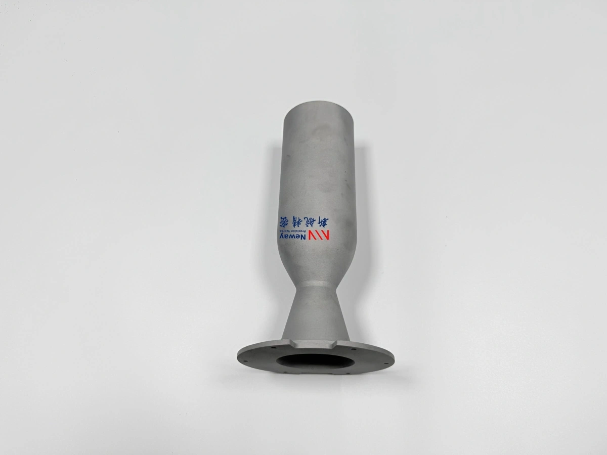
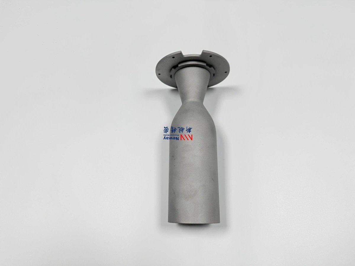
Direct Answer: Aerospace Combustion and Exhaust Parts Manufacturing
NewayAeroTech manufactures aerospace combustion and exhaust parts for aircraft engines, UAV turbines, and high-temperature propulsion systems. Depending on the component design, material grade, wall thickness, cooling features, and inspection requirements, the manufacturing route may include superalloy casting, CNC machining, EDM, deep hole drilling, heat treatment, surface preparation, post-processing, and final inspection.
Our aerospace combustion and exhaust parts manufacturing support can cover:
Combustion liners and combustion chamber liners
Flame tubes and thin-wall combustion structures
Transition ducts and hot gas transfer ducts
Exhaust cones and aerospace exhaust components
Heat shields and thermal protection parts
High-temperature combustion chamber components
Prototype and small-batch combustion and exhaust parts
The goal is to deliver high-temperature aerospace components with controlled wall thickness, stable geometry, clean cooling features, reliable material condition, coating-ready surfaces, and inspection documentation.
Typical Aerospace Combustion and Exhaust Components
Aerospace combustion and exhaust components work together to manage flame, hot gas flow, cooling air, thermal protection, and exhaust discharge. These parts are used in aircraft engines, UAV turbine systems, small propulsion systems, and aerospace development engines.
Typical components include:
Combustion liners for flame containment and thermal protection
Flame tubes for combustion stabilization and hot gas management
Transition ducts that guide hot gas toward downstream turbine or exhaust sections
Exhaust cones and exhaust ducts for high-temperature gas discharge
Heat shields used to protect nearby structures from direct thermal exposure
Cooling sleeves, rings, brackets, caps, and combustion chamber hardware
For UAV turbine and small aero engine projects, these parts are often produced for prototype testing, combustion validation, coating trials, or small-batch production. This requires flexible manufacturing and practical engineering review before tooling or production begins.
Operating Environment of Combustion and Exhaust Parts
Aerospace combustion and exhaust parts operate in a severe high-temperature environment. They are exposed to combustion gas, oxidation, thermal cycling, vibration, exhaust gas erosion, local hot spots, pressure fluctuation, and cooling airflow.
Typical operating conditions include:
High-temperature combustion and flame exposure
Oxidation and hot gas corrosion on flame-facing and exhaust-facing surfaces
Repeated thermal cycling during start, acceleration, shutdown, and test operation
Vibration, acoustic loading, and pressure fluctuation
Exhaust gas erosion and local thermal concentration
Film cooling, dilution airflow, and impingement cooling effects
Thin-wall deformation caused by thermal stress and assembly constraint
Because of these conditions, combustion and exhaust parts must be manufactured around thermal management, oxidation resistance, cooling function, wall stability, and surface condition rather than only external geometry.
Manufacturing Challenges for Combustion and Exhaust Components
Aerospace combustion and exhaust components are difficult to manufacture because they often combine thin-wall structures, cooling holes, curved ducts, welded regions, heat shield features, and coating-controlled surfaces. Small errors can affect airflow, fit-up, combustion validation, thermal protection, or exhaust performance.
Main manufacturing challenges include:
Thin-wall stability during forming, casting, machining, and heat treatment
Cooling hole position, diameter, angle, and pattern consistency
Film cooling holes, dilution holes, slots, and airflow windows
Welded regions and heat-affected zone control when fabrication is required
Thermal deformation control in liners, ducts, flame tubes, and exhaust cones
Surface roughness and cleanliness before coating or engine testing
Coating allowance and masking control for holes, flanges, and interfaces
For prototype combustion systems, manufacturing feedback is especially important because the first parts may be used to validate airflow, combustion behavior, cooling performance, and thermal durability.
Manufacturing Routes for Aerospace Combustion and Exhaust Parts
Combustion and exhaust parts may require different process routes depending on geometry, wall thickness, alloy grade, cooling structure, and prototype stage. Some components are formed and welded. Some are machined from high-temperature alloy stock. Some complex components may use vacuum investment casting before CNC machining and post-processing.
NewayAeroTech supports vacuum investment casting for selected high-temperature components where near-net-shape geometry, integrated features, or complex superalloy casting is required. For flanges, brackets, nozzle hardware, ducts, heat shield interfaces, and local combustion features, superalloy CNC machining supports final dimensional accuracy.
A typical manufacturing route may include:
Review combustion liner, flame tube, exhaust duct, or heat shield design
Evaluate material, wall thickness, cooling holes, coating requirement, and inspection scope
Select forming, casting, CNC machining, EDM, drilling, welding, or combined process route
Produce the blank or thin-wall structure according to the selected route
Machine flanges, datum surfaces, mounting features, sealing areas, and local interfaces
Process cooling holes, dilution holes, slots, exhaust features, and airflow passages
Apply heat treatment, stress relief, cleaning, surface preparation, or post-processing
Inspect wall thickness, hole position, distortion, surface cracks, material condition, and coating readiness
Cooling Hole and Airflow Feature Control
Cooling holes and airflow features are central to aerospace combustion and exhaust part performance. They help control wall temperature, manage flame stability, protect heat shields, and reduce local hot spots in liners, flame tubes, transition ducts, and exhaust structures.
Superalloy deep hole drilling can support selected aerospace combustion and exhaust parts where long, narrow, or airflow-related holes are required. EDM may also be used for small holes, angled holes, thin-wall openings, slots, or tool-access-limited features in high-temperature alloys.
Cooling feature control should focus on:
Hole diameter and tolerance
Hole position, pattern, and spacing consistency
Hole angle and airflow direction
Edge quality, burr removal, and burn-through prevention
Wall thickness around holes, slots, and windows
Cleanliness before coating, assembly, or engine testing
Blockage prevention after coating preparation or surface treatment
If cooling holes are inaccurate or blocked, local wall temperature can rise and lead to thermal fatigue cracks, hot spots, coating damage, oxidation, or early part failure.
Material Strategy for Combustion and Exhaust Parts
Aerospace combustion and exhaust parts require high-temperature alloys with oxidation resistance, thermal fatigue resistance, fabricability, and dimensional stability. Material selection depends on combustion temperature, exhaust gas temperature, cooling strategy, coating system, engine size, and customer specification.
Common material options include Hastelloy X, Haynes 188, Inconel 625, Inconel 718, and Nimonic alloys. NewayAeroTech supports Hastelloy alloy vacuum investment casting for high-temperature oxidation-resistant combustion and exhaust components, Inconel alloy vacuum investment casting for nickel-based aerospace turbine parts, and Nimonic alloy vacuum investment casting for selected nickel-based high-temperature applications.
Material | Typical Application | Selection Consideration |
|---|---|---|
Hastelloy X | Combustion liners, flame tubes, exhaust ducts, and high-temperature gas path structures | Good oxidation resistance and fabricability for hot combustion environments |
Haynes 188 | Heat shields, liners, flame tubes, and severe thermal protection parts | Cobalt-based option for high-temperature oxidation and thermal stability |
Inconel 625 | Combustion hardware, exhaust components, and corrosion-resistant hot-section parts | Useful where oxidation resistance, corrosion resistance, and manufacturability are required |
Inconel 718 | Structural combustion hardware and selected high-strength thermal components | Suitable where strength and machining performance are important, depending on temperature |
Nimonic alloys | Selected aerospace combustion and exhaust components | Reviewed for nickel-based high-temperature performance requirements |
For prototype and flight-related development programs, material selection should be confirmed based on test temperature, duty cycle, oxidation environment, coating plan, and customer inspection requirements.
Surface Preparation and Superalloy Post Process
After forming, casting, CNC machining, EDM, or drilling, aerospace combustion and exhaust parts may require heat treatment, stress relief, deburring, polishing, cleaning, coating preparation, and final inspection. Surface condition is especially important because these components are exposed to combustion gas, exhaust flow, oxidation, and coating adhesion requirements.
NewayAeroTech supports superalloy post process for high-temperature aerospace components that require controlled finishing before delivery or testing.
Post-processing may include:
Heat treatment or stress relief according to alloy requirements
Deburring around holes, slots, cutouts, edges, and welded regions
Surface cleaning and oxide removal
Surface roughness control for coating preparation
Masking planning for coating-controlled holes, flanges, and interfaces
Cleaning airflow passages and cooling holes before inspection
Final visual, dimensional, and surface condition review
If coating is required, coating allowance should be planned before final hole processing and machining. Coating buildup may affect cooling hole diameter, airflow consistency, sealing surfaces, exhaust interfaces, and assembly fit.
Inspection Focus for Combustion and Exhaust Components
Inspection for aerospace combustion and exhaust parts should verify thin-wall geometry, cooling function, material condition, surface quality, and assembly fit. The inspection plan should be confirmed before production because prototype validation and flight-related development programs may require specific records.
Inspection Item | What to Check | Why It Matters |
|---|---|---|
Wall thickness | Combustion liners, flame tubes, ducts, exhaust cones, and heat shields | Prevents weak zones, burn-through, and thermal deformation risk |
Hole position | Cooling holes, dilution holes, film cooling holes, exhaust airflow features | Controls airflow distribution and local wall temperature |
Surface cracks | FPI for cracks, open defects, heat-affected areas, and high-stress regions | Reduces risk before coating, assembly, or engine testing |
Dimensional distortion | Roundness, contour, flange alignment, duct geometry, exhaust geometry | Ensures correct fit-up and gas path geometry |
Material verification | Alloy grade, chemical composition, material record, heat treatment condition | Confirms material compliance and traceability |
Coating readiness | Cleanliness, roughness, oxide removal, masking surfaces, edge quality | Supports coating adhesion and high-temperature service behavior |
Additional inspection may include CMM measurement, visual inspection, weld inspection, surface roughness reports, cooling hole reports, hardness testing, and customer-specific first article documentation.
Prototype Combustion and Exhaust Validation Support
Aircraft engine and UAV turbine combustion and exhaust projects often begin with prototype testing. The first parts may be used for combustion validation, thermal response evaluation, exhaust flow testing, cooling hole optimization, coating trials, or engine bench testing.
Prototype combustion and exhaust parts can help customers validate:
Combustion liner geometry and flame tube structure
Cooling hole layout and airflow consistency
Heat shield performance and local thermal protection
Exhaust duct or exhaust cone thermal stability
Material oxidation resistance and heat treatment response
Surface condition before coating or high-temperature testing
Fit-up between liner, transition duct, fuel nozzle, heat shield, and exhaust hardware
For UAV turbine systems and small aero engines, fast prototype iteration is often important. NewayAeroTech can review the manufacturing route, identify risk points, and support small-batch production after prototype validation.
RFQ Checklist for Aerospace Combustion and Exhaust Parts
To quote aerospace combustion and exhaust parts accurately, customers should provide design, material, inspection, and testing information during the RFQ stage.
A complete RFQ should include:
Engine type, combustion or exhaust system type, component name, part number, and revision level if available
2D drawings with tolerances, wall thickness, datums, and material notes
3D CAD models for liners, flame tubes, transition ducts, exhaust cones, heat shields, or exhaust ducts
Material grade, such as Hastelloy X, Haynes 188, Inconel 625, Inconel 718, or Nimonic alloy
Manufacturing route preference, such as forming, casting, CNC machining, EDM, drilling, welding, or post-processing
Cooling holes, dilution holes, film cooling holes, slots, exhaust windows, and airflow features
Heat treatment, coating preparation, surface finish, or cleaning requirements
Inspection requirements such as wall thickness report, hole position report, CMM, FPI, material report, or surface roughness report
Quantity for prototype, combustion validation, exhaust testing, small-batch production, or long-term supply
Delivery schedule, packaging, and documentation requirements
If the project is for prototype development, customers should also provide test objectives, temperature requirements, cooling strategy, coating plan, exhaust condition, and expected iteration schedule.
Conclusion
Aerospace combustion and exhaust parts manufacturing requires careful control of high-temperature alloy material, thin-wall geometry, cooling hole accuracy, oxidation resistance, exhaust heat protection, coating preparation, and inspection. These components include combustion liners, flame tubes, transition ducts, exhaust cones, heat shields, and high-temperature combustion chamber components.
NewayAeroTech supports custom aerospace combustion and exhaust parts manufacturing for aircraft engines, UAV turbines, small aero engines, prototype combustion validation, exhaust testing, and small-batch aerospace propulsion projects. Our capabilities include vacuum investment casting, superalloy CNC machining, EDM, deep hole drilling, heat treatment, post-processing, material verification, wall thickness inspection, FPI, CMM inspection, and final documentation.
For aerospace combustion and exhaust parts quotation, please send combustion liner, flame tube, exhaust duct, heat shield, or transition duct drawings, 3D CAD files, material requirements, cooling hole details, prototype requirements, inspection standards, quantities, and delivery targets. NewayAeroTech can review the most suitable manufacturing route for your high-temperature engine system project.
