What Challenges Arise When Using Ultrasonic Testing on Complex or Thick Turbine Blade Sections?
Geometric Complexity and Acoustic Access
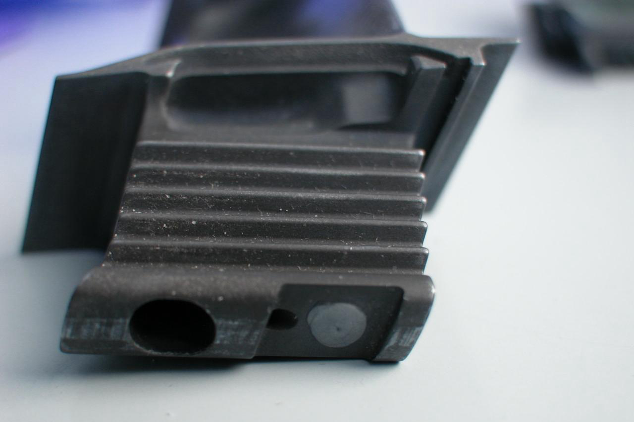
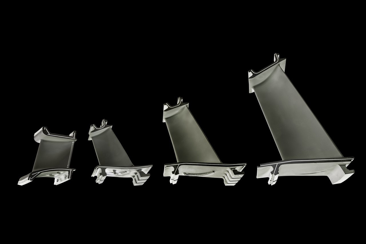
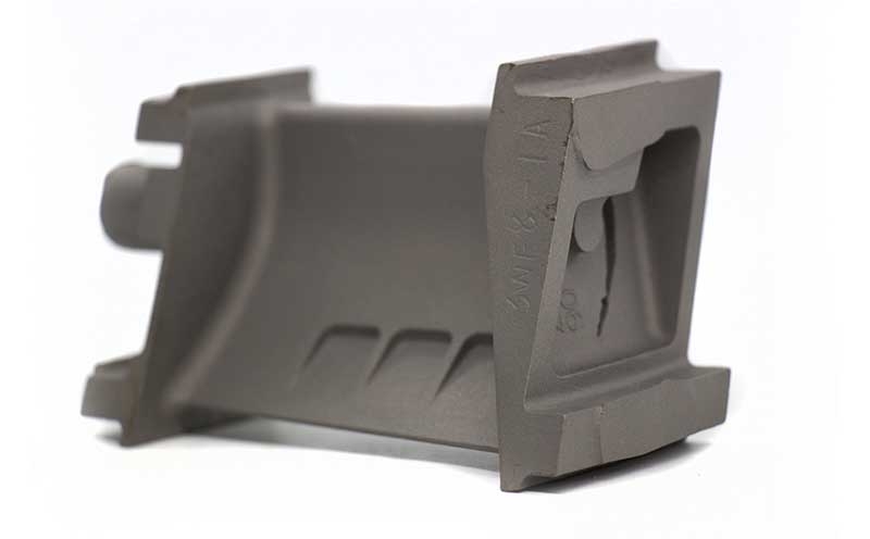
The primary challenge stems from the intricate geometry of modern turbine blades, such as thin, curved airfoils, shrouds, and internal cooling channels. These features cause severe ultrasonic beam scattering, refraction, and shadowing. Achieving consistent and normal acoustic coupling with a transducer probe across concave, convex, and twisted surfaces is exceptionally difficult. Complex geometries often create "blind spots" where defects can be masked. The need to inspect thick root sections and thin airfoils on the same component demands a versatile setup, often requiring multiple probe angles and specialized fixtures to maintain consistent contact, which is time-consuming and increases inspection complexity.
Material Attenuation and Noise
Superalloys used in single-crystal and directionally solidified castings have coarse, anisotropic grain structures. In thick sections, ultrasonic waves experience significant acoustic attenuation (signal loss) and scattering at dendritic boundaries. This grain noise can obscure subtle flaw signals, such as those from small inclusions or fine cracks. Differentiating between harmless microstructural noise and a critical defect requires advanced signal processing and highly skilled interpretation. The anisotropic nature of single-crystal materials also means sound velocity varies with crystallographic orientation, complicating depth calculations and flaw sizing if the orientation is not precisely known.
Equipment and Coupling Limitations
Inspecting thick sections necessitates using low-frequency probes to penetrate deeper, but this reduces sensitivity to small defects. Maintaining stable couplant (water or gel) layers on vertical or overhead surfaces of a blade during automated scanning is a persistent practical challenge. For internal cooling channels, immersion testing or the use of specialized bore probes may be required, but access is often limited by channel diameter and curvature. The need to validate the inspection of complex investment castings often drives the requirement for custom-designed UT systems and representative reference standards with artificially induced defects for calibration, which are costly and complex to produce.
Data Interpretation and Process Integration
The interpretation of UT data from such components is highly specialist. Echoes from geometric features like fillets, cooling hole breaks, and changes in wall thickness can mimic flaw signals, leading to false calls. This requires sophisticated C-scan imaging and comparison with a known "golden part" or detailed CAD model. Furthermore, integration into the manufacturing workflow poses logistical challenges. UT is typically performed after Hot Isostatic Pressing (HIP) and before final precision machining or coating application. Any delay or uncertainty in UT results can bottleneck production. Despite these challenges, advanced techniques like Phased Array UT (PAUT) and Time-of-Flight Diffraction (TOFD) are critical for material testing and analysis to ensure the integrity of blades for aerospace and power generation applications.