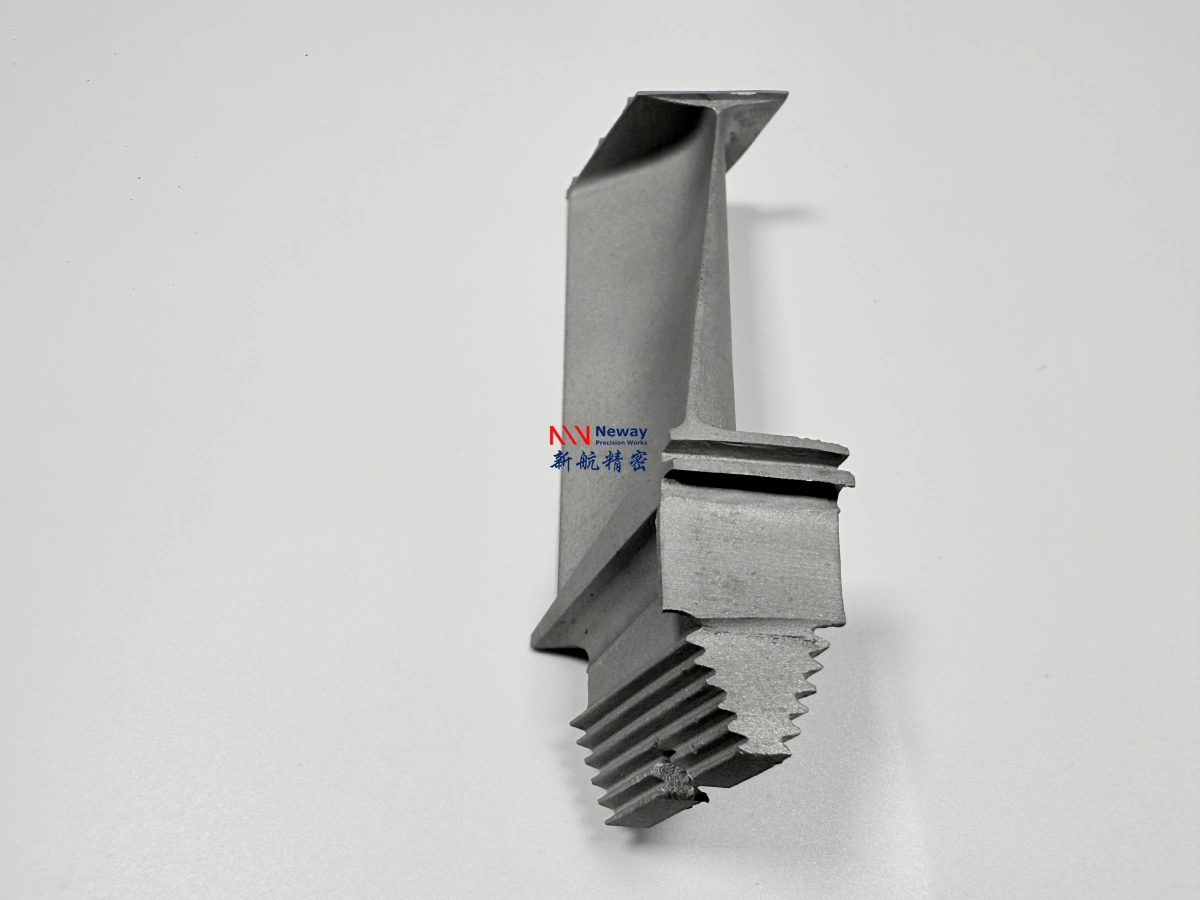
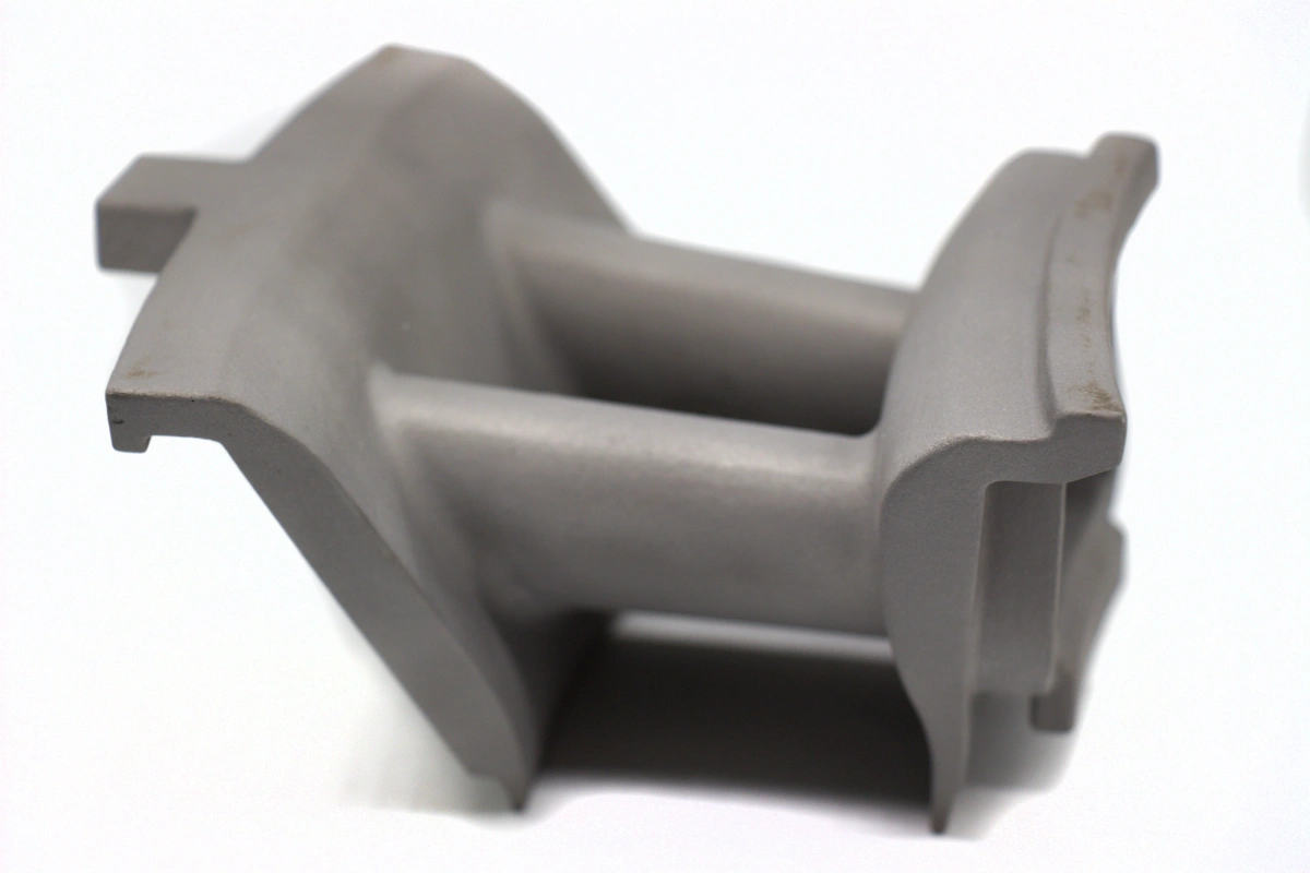
Gas Turbine Transition Pieces for Power Plant Repair and Replacement
NewayAeroTech supports custom gas turbine transition pieces, transition ducts, and transition liner replacement parts for power plant repair and maintenance projects. These components connect the combustion section to the turbine section and guide high-temperature combustion gas into the first turbine stage with controlled flow direction, sealing, and thermal protection.
For power generation turbine repair projects, transition pieces are not simple ducts. They operate under high-temperature gas impact, thermal cycling, vibration, thin-wall stress, oxidation, coating degradation, and assembly load. A reliable replacement transition piece must control material selection, forming or casting route, welding quality, CNC-machined interfaces, cooling features, surface condition, and final inspection.
NewayAeroTech provides power generation turbine replacement parts support for transition pieces, transition ducts, combustion-related hot section parts, and other gas turbine repair components made from drawings, used samples, 3D scan data, or turbine model information.
![]()
![]()
Direct Answer: Gas Turbine Transition Pieces for Repair and Replacement
NewayAeroTech can manufacture custom gas turbine transition pieces and transition ducts for power plant repair and replacement projects. Depending on the original design, material requirement, wall thickness, cooling features, and inspection standard, the manufacturing route may include high-temperature alloy forming, special alloy casting, vacuum investment casting for selected components, welded assembly, CNC machining, heat treatment, post-processing, and final inspection.
Our manufacturing support can cover:
Custom transition pieces for gas turbine repair
Replacement transition ducts for power generation turbines
Transition liner and hot gas path duct components
Superalloy transition piece manufacturing and finishing
Cooling hole, flange, sealing edge, and mounting interface processing
Small-batch repair parts and long-term spare transition duct supply
The goal is to provide transition piece replacement parts with controlled inlet and outlet geometry, thin-wall stability, sealing performance, cooling feature accuracy, coating-ready surfaces, and traceable inspection documentation.
Component Function of Gas Turbine Transition Pieces
A gas turbine transition piece transfers high-temperature combustion gas from the combustor to the turbine inlet. It must shape the gas flow, maintain stable passage geometry, protect the surrounding structure, and connect correctly with adjacent combustion and turbine hardware.
Transition pieces usually perform several functions at the same time:
Guide hot combustion gas from the liner outlet toward the turbine section
Control gas flow direction, distribution, and passage transition
Maintain sealing between combustion hardware and turbine inlet components
Support thermal expansion and vibration without excessive distortion
Provide cooling features or protective surfaces where required
Protect adjacent structures from direct high-temperature gas exposure
Because the transition piece directly affects hot gas delivery into the turbine, replacement parts must be manufactured with careful control of inlet contour, outlet contour, mounting flanges, sealing edges, cooling holes, and thin-wall surface condition.
Operating Conditions for Transition Ducts
Transition ducts operate between the combustion chamber and turbine section, where the temperature, pressure fluctuation, gas velocity, and thermal gradient are severe. These parts often experience both steady high-temperature exposure and repeated start-stop thermal cycles.
Typical service conditions include:
High-temperature combustion gas impact
Thermal fatigue from repeated heating and cooling
Oxidation and hot corrosion on gas-facing surfaces
Cooling air flow, film cooling, or impingement cooling effects
Vibration and acoustic loading from the combustion system
Thin-wall deformation caused by thermal stress and mechanical constraint
Coating degradation during long service intervals
These operating conditions explain why transition piece manufacturing must combine material performance, geometry control, surface preparation, and inspection instead of focusing only on the external shape.
Common Failure Modes of Gas Turbine Transition Pieces
Transition pieces can degrade during operation because they are exposed to high thermal load, combustion gas, vibration, and constrained assembly conditions. During power plant outage inspection, damaged transition ducts may require repair, refurbishment, or complete replacement.
Common failure modes include:
Thermal fatigue cracks near corners, welds, flanges, or high-stress transition areas
Burning, ablation, or local overheating on gas-facing surfaces
Thin-wall deformation, bulging, ovality, or loss of original contour
Oxidation, hot corrosion, or wall thinning after long service exposure
Coating spalling, peeling, or local coating loss
Mounting edge wear, flange distortion, or sealing face damage
Cooling hole blockage, edge damage, or airflow feature degradation
Weld repair zone cracking or local repair failure
When repair is no longer practical or the original geometry cannot be restored reliably, replacement transition pieces are required to protect turbine performance and maintenance safety.
Material Requirements for Transition Piece Replacement
Transition piece materials must resist oxidation, thermal fatigue, high-temperature strength loss, corrosion, and deformation. The alloy must also be compatible with forming, welding, machining, heat treatment, and coating preparation when these processes are required.
Common material considerations include:
Oxidation resistance under hot combustion gas exposure
Thermal fatigue resistance during start-stop cycles
High-temperature strength and dimensional stability
Weldability or repairability when the design includes fabricated joints
Compatibility with oxidation-resistant coating or thermal barrier coating systems
Availability in suitable sheet, plate, casting, or custom manufacturing forms
NewayAeroTech supports Hastelloy alloy vacuum investment casting for high-temperature and corrosion-resistant alloy applications. For nickel-based hot section parts, Inconel alloy vacuum investment casting can support material comparison and custom component development. For selected lightweight or high-strength aerospace applications, Titanium alloy vacuum investment casting may also be reviewed, although titanium is not normally selected for the hottest combustion gas path zones.
Manufacturing Route for Gas Turbine Transition Pieces
Transition pieces may be manufactured through forming, welding, casting, machining, or a combined route depending on the original design. Many transition ducts are thin-wall formed and welded structures, while selected sections, brackets, bosses, mounting features, or complex transition components may require casting or CNC machining.
A typical manufacturing route may include:
Review turbine model, transition piece drawings, old parts, or 3D scan data
Confirm material grade, wall thickness, coating requirement, cooling features, and inspection standard
Produce the transition duct body by forming, fabrication, casting, or combined manufacturing route
Weld or assemble liner sections, flanges, brackets, and transition structures where required
Machine mounting flanges, sealing edges, datum surfaces, and assembly interfaces
Process cooling holes, airflow features, slots, or local openings
Apply heat treatment, stress relief, or post-processing according to material requirements
Prepare surfaces for coating, cleaning, and final inspection
Inspect contour, wall thickness, welds, cooling features, dimensions, and surface quality
NewayAeroTech provides superalloy post-process for transition ducts to connect heat treatment, surface cleaning, coating preparation, finishing, and inspection into a controlled manufacturing workflow.
Casting and Special Alloy Options for Transition Components
Not every transition piece is fully cast. However, selected transition components may require casting when the geometry is complex, the part includes thick-to-thin transitions, or the design contains integrated mounting features, bosses, brackets, or flow-path structures that are difficult to fabricate efficiently.
Vacuum investment casting for gas turbine parts can support near-net-shape high-temperature alloy components where casting reduces material waste and improves geometry repeatability. For more demanding alloy requirements, special alloy casting for transition components can be reviewed when material behavior, wall thickness, and inspection requirements must be considered together.
Casting evaluation should consider:
Wall thickness variation and hot spot risk
Curved flow-path geometry and transition surfaces
Mounting bosses, brackets, flanges, and local reinforcement features
Machining allowance for sealing and assembly surfaces
Inspection access for internal and external defects
Compatibility with welding, coating, or post-processing steps
The final route should match the original design intent. For replacement projects, the goal is reliable function in the gas turbine, not simply reproducing the visible shape.
CNC Machining for Transition Pieces
CNC machining is required for transition piece features that control fit, sealing, and assembly. Even when the main duct body is formed or fabricated, flanges, mounting features, sealing edges, slots, and datum surfaces may require precision machining.
NewayAeroTech provides superalloy CNC machining for transition pieces, including high-temperature nickel alloys and corrosion-resistant alloys used in gas turbine hot section repair parts.
Typical CNC-machined features include:
Inlet and outlet mounting flanges
Sealing faces and contact edges
Datum surfaces for inspection and assembly alignment
Bracket interfaces and local attachment features
Controlled slots, windows, and boundary edges
Areas requiring flatness, profile, or location control
Machining strategy should account for thin-wall sensitivity. Incorrect fixturing or excessive cutting force can distort the transition duct and create fit-up problems during turbine assembly.
Cooling Feature Processing for Transition Ducts
Many transition pieces include cooling holes, dilution holes, slots, or airflow features that help manage wall temperature and protect the surrounding structure. These features must be controlled because hole size, location, angle, and cleanliness can influence cooling performance.
Superalloy deep hole drilling for cooling features can be reviewed for selected transition duct designs where deep or difficult airflow holes are required. EDM may also be used for small holes, narrow slots, curved-surface openings, or tool-access-limited features.
Cooling feature control should include:
Hole diameter and tolerance
Hole pattern, spacing, and angular direction
Edge quality and burr removal
Blockage risk from deposits, machining residue, or coating buildup
Wall thickness condition around holes
Inspection before and after coating when required
For used transition pieces, cooling holes may be blocked, enlarged, burned, or partially damaged. Reverse engineering should identify the original cooling function instead of copying damaged hole geometry from an old part.
Critical Geometry of Gas Turbine Transition Pieces
Transition pieces have complex geometry because they connect two different turbine sections while managing gas flow, thermal expansion, and sealing. Replacement parts must control both large surface shape and local assembly features.
Critical geometry includes:
Inlet contour and connection geometry to the combustion liner
Outlet contour and alignment with turbine inlet hardware
Mounting flanges, bolt areas, and bracket interfaces
Sealing edges, contact faces, and boundary surfaces
Thin-wall curved surfaces and transition radii
Cooling holes, slots, and airflow features
Coating allowance and masking surfaces
If the inlet or outlet contour is incorrect, gas flow may become uneven. If the flange or sealing surface is incorrect, assembly leakage or thermal stress may increase. If cooling features are inaccurate, local overheating can reduce service life.
Inspection for Transition Piece Replacement Parts
Inspection is essential for gas turbine transition pieces because the part combines thin-wall structure, welded or formed geometry, cooling features, high-temperature material, coating preparation, and assembly interfaces.
Inspection Item | What to Check | Why It Matters |
|---|---|---|
Contour inspection | Inlet shape, outlet shape, curved surfaces, transition geometry | Confirms gas path alignment and assembly fit |
CMM inspection | Flanges, sealing faces, mounting holes, datum surfaces | Verifies dimensional accuracy and installation interfaces |
Weld inspection | Cracks, undercut, lack of fusion, local distortion, repair zones | Supports structural reliability for fabricated transition ducts |
FPI | Surface cracks and open defects | Helps detect thermal fatigue or manufacturing cracks before delivery |
Cooling features | Hole position, diameter, angle, blockage, edge condition | Confirms cooling airflow and local thermal protection |
Material certificate | Alloy grade, chemical composition, heat treatment condition if required | Supports material consistency and customer traceability |
Inspection requirements should be confirmed before quotation because contour inspection, weld inspection, FPI, CMM, material testing, coating preparation review, and cooling hole reports can affect cost and lead time.
Reverse Engineering Support for Transition Duct Replacement
Many transition piece replacement projects begin with old parts, incomplete drawings, or 3D scan data. In these cases, reverse engineering must separate the original design from service damage.
NewayAeroTech can evaluate projects based on:
Original drawings and 3D CAD files
Used transition piece samples
3D scan data and reconstructed models
Photos showing cracks, burning, deformation, coating loss, or flange wear
Material analysis from old parts
Turbine model, combustor type, and operating condition
For used transition ducts, thermal deformation, worn mounting edges, cracked welds, coating loss, and distorted contours should not be copied directly. Functional geometry must be reconstructed according to gas flow, sealing, assembly, and thermal expansion requirements.
Supplier Value for Power Plant Transition Piece Repair
A qualified transition piece supplier should understand hot gas path function, thin-wall manufacturing, material selection, welding and forming control, CNC machining, cooling feature processing, post-processing, and inspection. The part should not be treated only as a duct or sheet metal shell.
NewayAeroTech supports transition piece repair and replacement projects by providing:
High-temperature alloy material review
Forming, casting, machining, and welded assembly route evaluation
CNC machining for flanges, sealing edges, and datum surfaces
Deep hole drilling or EDM review for cooling and airflow features
Heat treatment, stress relief, cleaning, and coating preparation support
Contour, weld, FPI, CMM, cooling feature, and material inspection planning
Prototype, small-batch repair parts, and long-term spare transition duct manufacturing
This integrated approach helps reduce communication gaps between forming, welding, machining, coating, and inspection suppliers, especially when power plant outage schedules require predictable delivery.
RFQ Checklist for Gas Turbine Transition Piece Replacement
To quote transition pieces and transition ducts accurately, customers should provide both technical drawings and service information. This helps the supplier evaluate material selection, manufacturing route, cooling feature processing, inspection cost, and delivery risk.
A complete RFQ should include:
Turbine model, combustor type, transition piece part number, and revision level
2D drawing and 3D CAD file if available
Used transition piece sample, photos, or 3D scan data if reverse engineering is required
Required material grade and acceptable alternatives
Wall thickness, inlet contour, outlet contour, flange, and sealing surface requirements
Cooling hole diameter, position, angle, pattern, and inspection requirements
Welding, heat treatment, coating, or surface preparation requirements
Inspection requirements such as contour inspection, weld inspection, FPI, CMM, material certificate, or cooling hole report
Quantity for prototype, repair batch, or long-term spare parts program
Delivery schedule, outage timing, packaging, and documentation requirements
If the project is based on a damaged transition piece, customers should identify crack areas, burned zones, worn flanges, coating loss, blocked cooling holes, repaired welds, and functional sealing surfaces. This helps prevent reverse engineering errors and supports more reliable replacement manufacturing.
Conclusion
Gas turbine transition pieces for power plant repair and replacement require careful control of high-temperature alloy material, thin-wall geometry, inlet and outlet contours, sealing surfaces, cooling features, welding quality, coating preparation, and final inspection. These components connect the combustion section and turbine section, so their geometry and surface condition directly affect hot gas path reliability.
NewayAeroTech supports custom transition piece and transition duct manufacturing from drawings, old parts, 3D scan data, or turbine model information. Our capabilities include forming route review, vacuum investment casting for selected gas turbine parts, special alloy casting, superalloy CNC machining, deep hole drilling or EDM for cooling features, post-processing, contour inspection, weld inspection, FPI, CMM, and final documentation.
For transition piece repair parts quotation, please send the turbine model, part number, 2D drawing, 3D file, sample photos, material requirement, cooling feature details, coating requirement, inspection standard, quantity, and delivery target. Our engineering team can review the most suitable manufacturing route for your power plant repair project.