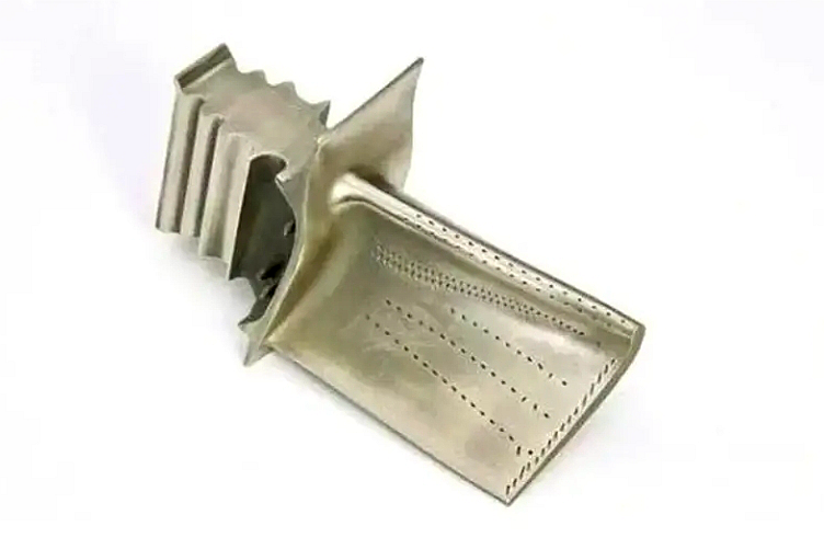
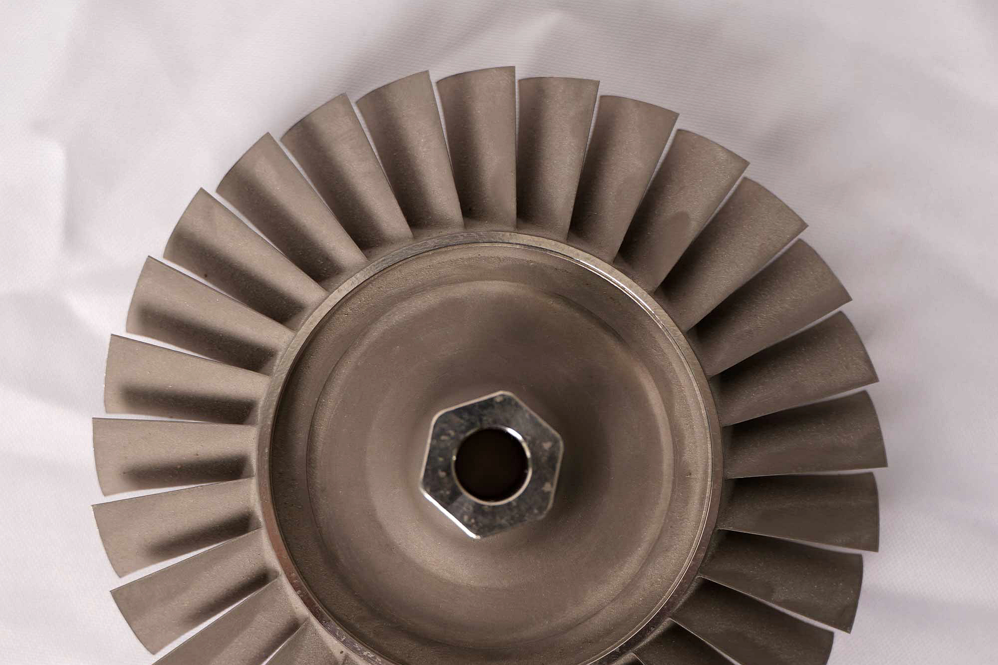
Reduce Downtime with TBC for High-Temperature Alloy Parts
Thermal barrier coating can support a maintenance strategy only when the coating, substrate, cooling features, and service damage remain inside an approved restoration envelope. An available coating process does not by itself shorten an outage. Incoming inspection, stripping, repair, heat treatment, machining, passage checks, reapplication, testing, transport, and engineering disposition can control the schedule.
For this RFQ, buyers should define the component and configuration, coating system, service history, known damage, outage milestones, lawful design authority, strip and recoat limits, minimum substrate wall, repair zones, cooling-feature requirements, qualification evidence, and decision owners. The supplier should quote conditional paths instead of assuming every used part can be recoated.
Map the Full Outage Path Before Quoting TBC Work
The maintenance calendar can include removal, cooling, cleaning, decontamination, transport, incoming photography, coating assessment, strip trials, substrate NDE, dimensional and wall inspection, engineering disposition, weld or braze repair, heat treatment, coating preparation, bond coat, top coat, final inspection, return shipment, installation, and commissioning.
Identify which operations are sequential and which can run in parallel. Fixtures, masks, coupons, replacement feedstock, and transport plans may be prepared while incoming inspection proceeds, but no work should bypass a hold point that determines repairability.
State response times expected from buyer engineering, because an unanswered disposition can exceed the coating application time. A supplier schedule should list dependencies and queue assumptions rather than present a single unconditional completion date.
Document Incoming Coating and Component Condition
Record part identity, coating zones, visible spallation, cracking, erosion, deposits, discoloration, edge lifting, blocked holes, prior local repairs, distortion, oxidation, and handling damage. Use consistent photographs, zone maps, scales, and orientation.
Where service data are available, include operating hours or cycles, temperature events, fuel or process chemistry, cooling issues, prior inspections, coating system, and strip/recoat history. These data do not automatically approve repair, but they help identify damage mechanisms and select inspection.
A used part may differ from the nominal drawing through wear, wall loss, blend, coating buildup, deformation, and earlier repair. Separate current condition from controlled design geometry before the quote assumes machining or coating stock.
Classify Damage Before Selecting Local Repair or Recoat
Damage finding | Potential route | Required decision evidence |
Small isolated top-coat chip in an allowed zone | Approved local repair may be considered | Boundary, bond-coat condition, cause and repair qualification |
Broad spallation or connected cracking | Strip and full system evaluation | Damage map, interface and substrate condition |
Erosion or edge recession | Geometry and wall review before coating decision | Profile, thickness and repair limit |
Deposits or chemical attack | Cleaning and material assessment | Deposit type, penetration, bond-coat and substrate condition |
Cooling-hole restriction | Controlled cleaning or restoration | CT, borescope, dimensions and flow evidence |
Oxidized, cracked or depleted substrate | Engineering disposition or replacement path | NDE, wall, metallography or other approved assessment |
Do not describe every visible coating loss as the same failure. Impact, thermal cycling, oxide-scale growth, bond-coat depletion, preparation, thickness variation, erosion, deposits, substrate strain, cooling loss, and edge design require different corrective actions.
The triage output should be local repair, strip and recoat, further evaluation, or no restoration. Define stop conditions before the supplier incurs downstream coating cost.
Validate the Strip Method Against Substrate Loss
Chemical, mechanical, or other approved removal methods can affect substrate chemistry, wall, profile, surface, cooling-hole edges, welds, and remaining bond coat. The strip plan should identify material system, previous cycles, removal endpoint, masks, monitoring, and maximum permitted substrate loss.
Use trials or representative coupons when the substrate and coating history are uncertain. Inspect after top-coat removal and again after bond-coat removal if required. Coating residue, depleted zones, oxide penetration, cracks, and embedded media need disposition before preparation.
Track cumulative strip and recoat cycles. A method acceptable once may consume too much wall or alter surface after repeated refurbishment. The component record should retain each cycle and repair.
Inspect the Bare Substrate Before Reapplication
After stripping, inspect surface indications, dimensions, wall thickness, cooling features, weld or braze zones, oxidation, depletion, and cleanliness. Coating should not be applied over an unaccepted crack, inclusion, porosity, undersized wall, blocked passage, or unapproved repair.
Select FPI, radiography, CT, ultrasonic methods, CMM, scanning, wall measurement, chemistry, hardness, or metallography by the defect question and geometry. State coverage and known blind zones. A generic NDE certificate is not enough.
Use material testing and analysis only where it changes disposition. Early targeted evidence can prevent spending on weld repair, heat treatment, and recoating for an ineligible part.
Control Approved Substrate Repair Before TBC
If weld, braze, blend, or dimensional restoration is permitted, define zones, excavation, filler or braze material, heat input, maximum cycles, minimum wall, final profile, thermal treatment, and NDE. The repaired area may need special preparation or coating qualification.
Re-establish geometry and datums after thermal processing. Leave controlled stock for finishing without cutting through a repair boundary or below minimum wall. Inspect the final substrate surface before coating.
A local substrate repair can change heat flow, residual stress, chemistry, surface, and coating attachment. Record repair maps and ensure coupons or validation represent the approved condition where required.
Rebuild the Approved Bond-Coat and Top-Coat System
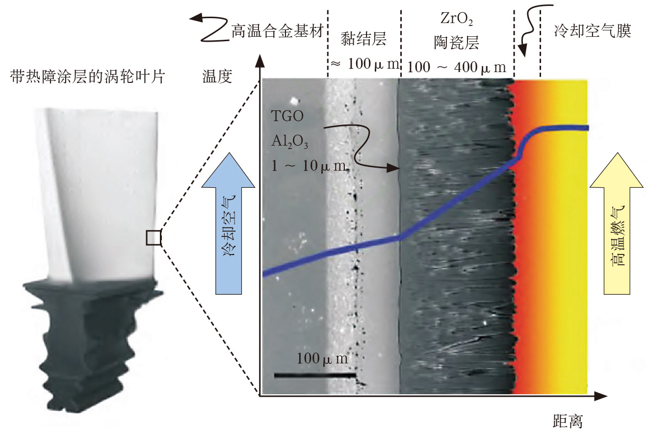
TBC reapplication should follow the approved substrate preparation, bond coat, diffusion or thermal cycle, ceramic material, application method, thickness or structure, zones, masks, edge terminations, and cooling-hole controls.
Do not substitute powder, bond-coat chemistry, APS for EB-PVD, or another material based only on availability during an outage. A material or method change needs the buyer's technical review and may require comparative qualification.
Record coating material lots, component load position, equipment, critical parameters, masks, coupons, and any local rework. The recoat should be traceable as a new material state, not merged with the original record.
Protect Cooling Features and Assembly Interfaces
Cooling holes, slots, internal passages, seal faces, fits, threads, datum pads, and mounting interfaces can be damaged by stripping, blasting, overspray, masking, and coating removal. Define protected zones and inspection after each operation that can change them.
Where hole reopening is approved, control method, position, edge, recast or damage, wall, and final coating termination. Use CT, borescope, dimensional checks, cleanliness, or flow testing as required. Restored diameter alone may not prove direction or internal condition.
Mask design and removal should avoid residue, chipping, or edge lifting. Inspect coating transitions and mating faces before packaging.
Standardize Repair Classes for Repeat Outages
For recurring part numbers, define repair classes by zone, coating damage, bond-coat condition, substrate wall, oxidation, cooling feature, prior cycles, strip method, substrate repair, recoat system, and inspection. This can reduce repeated engineering only for parts inside the qualified envelope.
Use maps and numerical limits so inspection assigns classes consistently. Unexpected crack patterns, severe deposits, overheating, prior unauthorized repairs, or unknown configuration should return to engineering review.
Trend yield, additional evaluation, strip cycles, substrate repair, coating rework, and rejection by class. The data can improve spares planning and reveal when new manufacture is preferable.
Control Outside Sources and Critical-Path Handoffs
Stripping, NDE, welding, heat treatment, machining, coating, testing, and transport may be performed by different sources. Use one controlled traveler with part identity, input condition, completed work, remaining work, hold points, protected features, records, and deviation status.
Confirm equipment envelope, furnace or coating load, fixture and mask availability, feedstock, coupon preparation, laboratory queue, and shipping before committing the outage plan. The longest queue can be outside the coating booth.
Packaging should protect bare substrate, bond coat, ceramic, edges, holes, and machined interfaces at each handoff. Receiving inspection should record transit damage before another process hides the cause.
Use First-Article Recoat to Establish the Real Route
The first refurbished component should capture incoming damage, strip effort, substrate loss, engineering time, repair, thermal cycles, preparation, coating, passage work, inspection, rework, actual queue, and documentation. Review both technical result and route duration.
Qualify representative coupons or component zones for thickness, layer structure, interface, thermal cycling, or other required evidence. A coupon must use representative substrate condition and follow the same strip, preparation, material, application, and thermal sequence.
Update the repair class and schedule assumptions from actual results. Do not extrapolate one clean first article to parts with more severe service damage.
Plan Spares and Batches Around Repair Uncertainty
Inspect a sample of a returning fleet or batch early to estimate damage distribution and rejection risk. Maintain individual identity because used parts do not share the same condition. Group only parts with compatible restoration routes and coating systems.
For critical outages, the buyer may pursue repair and replacement paths in parallel. The supplier should provide technical decision milestones where the fallback remains possible. Inventory and operating decisions stay with the responsible authority.
New manufacture may be preferable when repeated strip loss, broad substrate degradation, uncertain configuration, low restoration yield, or qualification cost dominates. Coating capability should not force every part into the recoat path.
Inspect the Final Coating and Release Package
Final inspection can include coverage, thickness, appearance, edge and mask condition, cooling holes, flow, geometry, layer sections, thermal or adhesion-related tests, substrate-repair NDE, cleanliness, and packaging as specified. Recheck features affected by the full restoration route.
The release package should link incoming condition, disposition, strip, substrate inspection, repairs, thermal records, coating materials and process, coupons, tests, final inspection, nonconformance, and shipment to the component identity.
The supplier should state what was restored and measured. It should not convert the recoat result into a service interval or system-efficiency promise without the buyer's design and operating basis.
Send a Downtime-Focused TBC RFQ
Provide component and configuration, drawing and coating definition, substrate alloy and condition, service and repair history, known damage, outage milestones, strip and substrate-loss limits, repair zones, minimum wall, cooling features, approved bond coat and top coat, application method, inspection, tests, quantities, spares strategy, records, transport, decision owners, and change control.
Request separate lines for incoming gate, engineering review, strip trials, full stripping, substrate inspection, repair, heat treatment, machining, masks, coating, coupons, tests, passage checks, documentation, shipping, and conditional rework. Ask for assumptions and stop points.
A credible plan reduces avoidable delay by making damage decisions early and controlling every restoration handoff. It does not promise that TBC alone will shorten downtime before the used component is evaluated.
Related FAQs
How Does TBC Extend the Lifespan of High-Temperature Alloy Components?
APS vs. EB-PVD: A Comparison of Thermal Barrier Coating (TBC) Application Methods
Thermal Cycling Testing: Evaluating Thermal Barrier Coating (TBC) Durability and Lifespan
Can Damaged TBC Coatings Be Repaired, and What Methods Are Used?