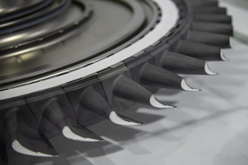
Nickel-Based Alloy Control Rod Modules Production Unit
A control rod module component cannot be quoted responsibly from a part name and nominal alloy alone. The buyer must define whether the requested item is a connector, guide feature, spacer, end fitting, support, sleeve, housing, or another manufactured element, then identify its relationship to the controlled assembly. The component supplier evaluates manufacturability to buyer-controlled data; system function, operating limits, and final design approval remain with the responsible engineering authority.
For nickel-based alloy parts, the quotation depends on exact material specification, product form, geometry source, dimensional chain, joining boundary, surface condition, inspection evidence, documentation, and first-article requirements. These inputs should be agreed before raw material, tooling, or a long-lead special process is committed.

Define the Manufacturing Boundary Before Sending the RFQ
State exactly what the supplier must deliver: raw blank, rough-machined part, finished component, weld-ready subcomponent, or assembled module. Identify any buyer-supplied items and the party responsible for final assembly. A supplier quoting only a machined connector should not assume responsibility for the complete control mechanism, while a module quotation needs a clear interface for every included part.
Provide the controlled drawing, reference model, revision, and characteristic numbering. Mark functional datums, mating features, guide surfaces, joining preparations, threaded interfaces, and surfaces that remain as produced. If a sample is supplied, explain whether it is an unused master, an inspection reference, or a used component. Wear, deformation, deposits, previous finishing, and disassembly damage can make a service sample unsuitable as final geometry.
Include buyer-approved environmental and loading inputs only to the extent needed for manufacturing review: temperature, relevant fluid exposure, irradiation-related material requirements specified by the buyer, thermal cycling, wear interfaces, and handling restrictions. The supplier should not derive system design criteria or choose acceptance limits that belong to the end user.
Approve Exact Material and Product Form
Specify the complete alloy designation and governing purchase requirement. Nickel alloys such as Alloy 600, 625, 718, or another approved grade can have very different strengthening mechanisms, corrosion behavior, heat treatments, and fabrication responses. These grades are examples of distinct material systems, not interchangeable options. The buyer must approve the grade and any chemistry, grain-size, cleanliness, or mechanical-property limits.
Product form is equally important. Wrought bar, tube, plate, forged stock, cast stock, and powder-derived material have different specifications and test locations. A long sleeve developed from tube should not be switched to a casting because both share a nominal chemistry. If vacuum investment casting is being considered for an integrated fitting, the drawing and material specification must permit a cast product form.
Define material traceability and evidence at the RFQ stage. State whether the package requires heat identity, purchase records, chemistry, mechanical results, heat-treatment records, supplementary tests, or retained samples. The supplier should show how cut blanks and subcomponents remain linked to the original heat and lot through machining and assembly.
Choose the Route by Geometry and Product-Form Requirement
Component condition | Manufacturing question | RFQ output |
Long sleeve or guide | Is qualified tube or bar available with enough stock for straightness and final bore control? | Stock condition, cut plan, straightening and dimensional sequence |
Heavy connector or end fitting | Does the approved product form favor forged stock or a near-net blank? | Blank drawing, forging or casting route, machining allowance |
Integrated branches or complex pockets | Can casting reduce joints while preserving inspectability and cleanability? | Gating and core concept, NDE zones, passage verification |
Thin precision spacer | Is sheet or bar machining less risky than a complex near-net route? | Fixture plan, distortion control, edge and surface requirements |
Joined subassembly | Who owns fit-up, joining instructions, distortion control, and final inspection? | Interface drawing, responsibility matrix, examination sequence |
Precision forging may suit a compact high-load connector when the approved product form and geometry support directional working. Casting may suit an integrated shape with difficult external contours. Machining from wrought stock can be the most reviewable route for sleeves, threaded features, and accessible precision interfaces. The supplier should select one route against the actual risk instead of listing every process as equivalent.
Quantity and development status affect the route. Provide prototype quantity, first-article quantity, expected production lot, and annual demand. Separate tooling, fixtures, development samples, destructive test material, and recurring part price. This allows procurement to see whether a route is economical only at production volume or also suitable for a validation lot.
Control Straightness, Concentricity, and Long Features
Long sleeves and guide features require a datum strategy that survives material removal. The RFQ should state how straightness, runout, concentricity, wall thickness, and end-feature relationships are defined on the controlled drawing. Specify the free-state or restrained measurement condition when it affects the result. A supplier cannot quote a meaningful inspection sequence if the drawing does not show which axis governs the mating assembly.
Superalloy CNC machining must account for work hardening, low thermal conductivity, tool pressure, and stress release. Removing stock from one side of a slender part can move the centerline. A practical route may alternate roughing passes, preserve temporary support features, perform approved intermediate stabilization, and finish critical diameters only after the part has reached a stable condition.
Deep bores and small intersecting features need defined tool access, chip removal, breakthrough condition, and burr control. When deep-hole drilling or EDM is proposed, agree the inspection method for diameter, drift, intersection, internal surface, and any recast-layer restriction. Hidden burrs or blocked passages are manufacturing risks, not cosmetic details.
Establish Joining and Assembly Responsibility
A module can include threaded, pinned, welded, brazed, mechanically locked, or otherwise joined interfaces defined by the buyer. The RFQ should identify which party controls fit-up, joining materials, procedure approval, tooling, distortion correction, and examination. The component manufacturer should supply to the specified interface without implying authority over the final reactor-system assembly.
Show joint preparations, root faces, alignment features, protected surfaces, and allowed manufacturing stock on the drawing. If matched components must remain paired, define identification and handling. If the buyer supplies one side of the interface, include its controlled envelope and inspection status so the supplier does not compensate for an unknown mating-part condition.
Joining can change straightness and final feature relationships. State whether final machining occurs before or after joining and which datums are re-established afterward. The inspection plan should include the pre-join and post-join characteristics that reveal distortion rather than relying only on a final overall length.
Sequence Heat Treatment, Finishing, and Cleanliness
The approved alloy and product form determine the permitted heat-treatment condition. Link each cycle to its position in the route: incoming stock, formed blank, rough-machined part, joined subassembly, or finished component. The supplier should identify how furnace loading, quenching or cooling, and subsequent machining can affect distortion and surface condition.
Surface finishing instructions should distinguish functional guide surfaces, joining areas, threaded features, and noncritical exterior surfaces. Define roughness on the controlled drawing and state whether polishing direction, edge break, or local blending is restricted. A global “smooth finish” note is not enough for a component with sliding, sealing, and joining functions.
Cleanliness requirements may cover machining coolant, abrasive residue, penetrant residue, heat-treatment scale, free-iron contamination, and handling materials. Identify blind holes and internal volumes that need flushing or borescope review. Packaging should protect finished surfaces and preserve part identity without introducing incompatible material.
Match Inspection Evidence to Each Manufacturing Risk
Build the inspection plan from the route. Dimensional inspection controls datum relationships, straightness, bore position, thread form, wall thickness, and mating envelopes. Liquid penetrant testing may address specified surface-breaking indications. Radiography or ultrasonic testing is useful only where product form, geometry, and an agreed technique provide meaningful coverage. CT may support complex internal geometry when required by the buyer.
Material testing and analysis can include chemistry, tensile or hardness tests, metallography, cleanliness checks, or other specification-driven evidence. Every result should identify the heat, lot, processing condition, sample source, and applicable requirement. Do not treat an unrelated stock certificate as evidence for a characteristic created by later heat treatment or joining.
The documentation list should distinguish inspection results, route records, material evidence, special-process records, deviation dispositions, and final traceability. Ask for the records needed to approve the part while avoiding vague requests for “full documentation,” which different suppliers may interpret differently.
Use First Article to Prove the Route
A first article should demonstrate the complete proposed route, not only final dimensions. Review material identity, blank condition, machining sequence, straightness control, joining interfaces, heat treatment, finishing, cleanliness, NDE, and traceability. If destructive examination or sectioning is required, define the representative sample and its relationship to the production parts.
Any deviation, rework, blending, or repair request should cite the exact characteristic and designated approval authority. Record the correction, repeat inspection, and any downstream operation affected. An adjustment that restores one diameter may still change straightness, wall thickness, or surface condition.
After acceptance, define change-notification triggers for material source, blank route, tooling revision, heat treatment, machining setup strategy, joining source, special processing, and inspection method. The accepted first article must remain connected to repeat production through controlled process identity.
Control Rod Module RFQ Checklist
Send the controlled drawing and model, revision, exact alloy and product form, component and assembly boundary, quantity by phase, buyer-supplied items, blank or finished scope, datum system, long-feature requirements, joining interfaces, delivery condition, surface and cleanliness requirements, inspection coverage, documentation list, and first-article hold points.
Request separate quotation lines for material, tooling, development units, recurring parts, machining, joining, post-processing, inspection, destructive samples, records, and packaging. A responsibility matrix should identify each supplier and buyer action. That prevents hidden assumptions from moving into production after the technical review.
Related FAQs
What Are the Key Materials Used in the Manufacturing of Control Rod Modules?
How Does Vacuum Investment Casting Improve the Quality of Control Rod Modules?
What Role Does Powder Metallurgy Play in Control Rod Module Manufacturing?
What Are the Key Testing and Inspection Methods for Control Rod Modules?
Why Is Post-Processing Critical in the Production of Control Rod Modules?