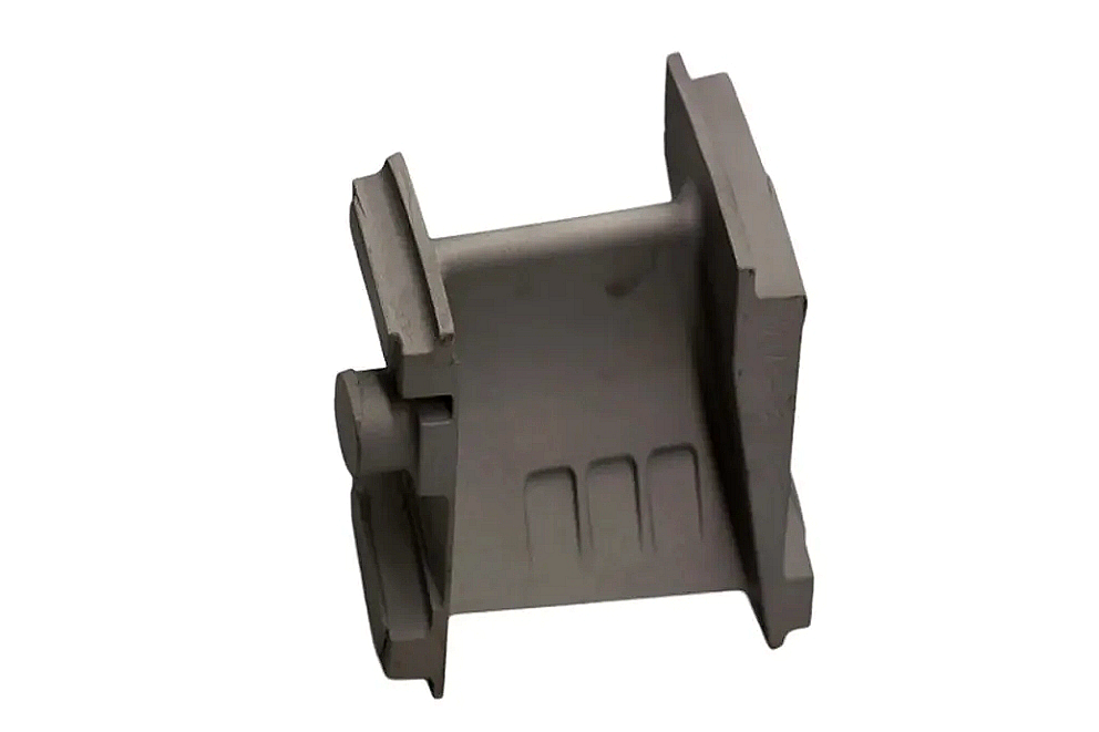
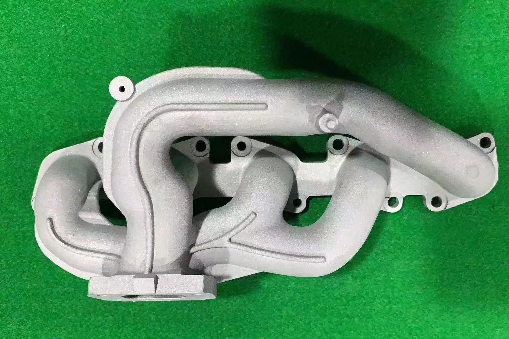
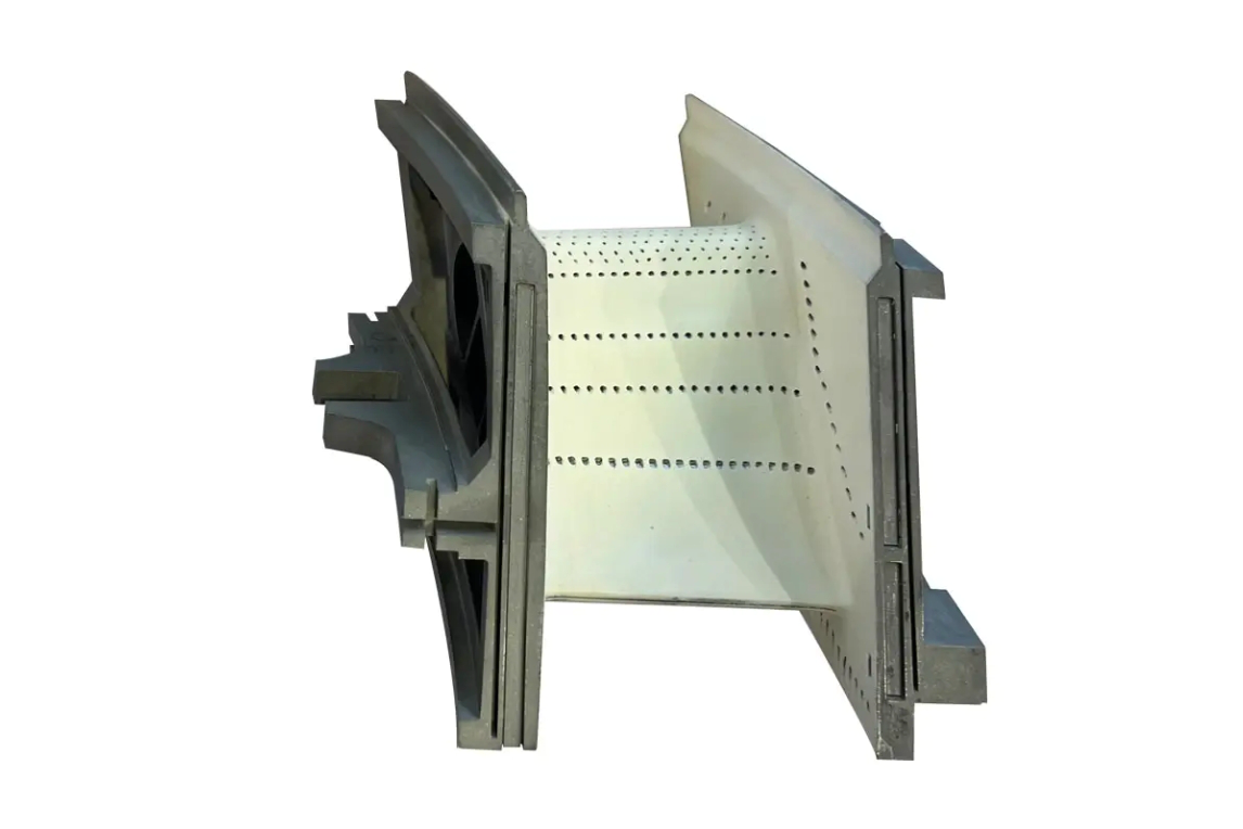
Aerospace-Grade Metal Pump System Assemblies Supplier
“Aerospace-grade” does not by itself define a pump component requirement. A supplier needs the exact alloy, product form, drawing revision, hydraulic interface, rotational features, inspection plan, and documentation scope. The RFQ should also state whether the purchase covers a casing, impeller, diffuser, inducer, wear ring, shaft sleeve, seal carrier, individual blank, or a complete buyer-defined assembly.
Pump quotations become unreliable when one supplier assumes a rough casting and another assumes a machined, balanced, inspected subassembly. Buyers should divide the scope into material, blank production, machining, joining, surface condition, component inspection, assembly work, and functional evidence. Each boundary changes tooling, fixtures, setup count, and first-article work.
Define the Pump Component and Supplier Responsibility
Name every included part and identify buyer-supplied items. A casing-and-cover set requires matched interface control; an impeller quotation may include only the blank or may extend through bore machining and balancing; a seal carrier may require mating-envelope data. State who owns bearings, seals, shafts, fasteners, and final assembly. The component supplier should not infer complete pump-system responsibility from a model containing surrounding geometry.
Provide the controlled 2D drawing and reference model with revision alignment. Mark pressure-containing walls, wetted surfaces, seal faces, bearing or shaft datums, threads, fits, joining preparations, and as-cast surfaces. If a used pump part is the only physical reference, describe corrosion, cavitation, wear, deformation, deposits, and previous repair. A service sample can reveal interfaces but should not be copied as final geometry without buyer approval.
Hydraulic duty, pressure, speed, temperature, fluid chemistry, solids content, cleaning media, and upset conditions should come from the responsible system designer. The part supplier uses these approved inputs to review manufacturability and material requirements; it should not create pump performance criteria or acceptance limits on the buyer’s behalf.
Approve Alloy and Product Form by Exposure Zone
Different pump parts can need different materials. A wetted casing may be governed by corrosion and castability, an impeller by corrosion plus cavitation or erosion exposure, a shaft sleeve by wear and galling, and a high-temperature seal carrier by dimensional stability. Specify exact grades rather than broad terms such as nickel alloy, cobalt alloy, or titanium alloy.
The product form must match the purchase requirement. Cast, forged, wrought, and powder-derived material with similar nominal chemistry can follow different specifications and test routes. A compact impeller may suit vacuum investment casting; a heavily loaded hub may be reviewed for precision forging; an accessible sleeve may be machined from wrought stock. The buyer must approve any change from the drawing’s specified product form.
State heat and lot traceability, required material reports, heat-treatment evidence, and supplementary tests. If multiple materials are assembled, define how each identity remains connected to its part number and final assembly record. Material substitution should be a controlled buyer decision, not a shop-floor response to stock availability.
Choose a Route for Each Pump Part
Part or feature | Dominant manufacturing risk | RFQ evidence |
Volute casing or curved manifold | Core position, wall continuity, feeding, pressure boundary | Casting layout, core control, radiographic zones, machining stock map |
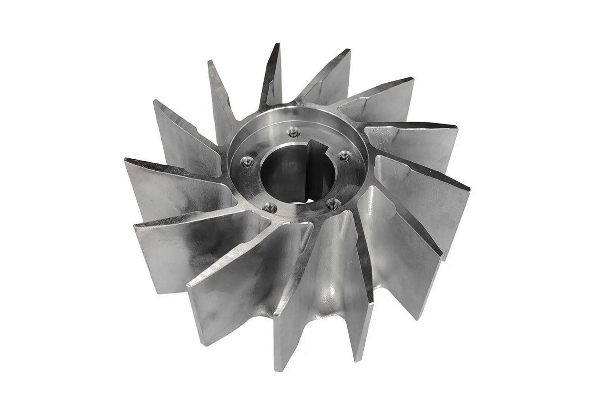
Closed impeller | Blade fill, internal cleanup, hub soundness, balance stock | Wax/core strategy, passage inspection, datum and balance plan |
Diffuser or guide vane ring | Vane position, throat area, concentricity | Dimensional method, throat checks, machining sequence |
Wear ring or shaft sleeve | Material condition, roundness, surface finish, galling risk | Stock form, datum plan, final inspection method |
Seal carrier or cover | Flatness, register relationship, bolt pattern, leakage path | Machining setup, CMM plan, sealing-surface protection |
A supplier should quote the selected route rather than list casting, forging, machining, and additive manufacturing as interchangeable options. Quantity, envelope, wall thickness, passage access, product-form requirement, and inspection coverage determine the practical choice. Provide development quantity, first-article quantity, production lot, and annual demand so tooling and recurring cost can be separated.
For prototype work, distinguish a form-and-fit model from a production-intent metal part. A polymer model may help assembly review but cannot establish cast soundness, machining distortion, material response, or pressure integrity. A production-intent first article must use the proposed material and route unless the buyer explicitly approves a limited-purpose deviation.
Control Impeller Cores, Blades, and Balance Stock
An impeller or inducer combines thin blades with a heavy hub and shroud. The casting layout must fill the blade edges, feed the hub, support any ceramic core, and leave removable gates without damaging flow surfaces. Mark surfaces where gate attachment is prohibited and specify whether blade leading and trailing edges are as cast, blended, or machined.
Closed passages need defined core prints, exit access, decoring method, and residual-media verification. State throat dimensions, local restriction limits, and surfaces requiring visual, borescope, radiographic, CT, or flow comparison evidence. Nominal outer dimensions do not prove that internal passages are open or evenly formed.
Leave balancing stock only in approved locations. The supplier needs the final bore datum, axial reference, rotational direction if relevant, and the buyer-defined balance requirement. Removing material from an arbitrary blade surface can change the hydraulic contour. The drawing should identify permissible correction zones and any post-correction inspection.
Machine from Functional Pump Datums
Casing machining should connect the main bore, seal face, bearing or shaft centerline, flange faces, and bolt patterns through a stable datum system. Impeller machining should control bore, hub faces, outside diameter, and any balance feature relative to the rotational axis. A general casting allowance does not replace a feature-by-feature stock map.
Superalloy CNC machining must account for work hardening, interrupted cuts, thin-wall movement, and low thermal conductivity. Rough machining a casing can release residual stress and move a seal register. A practical sequence may rough critical surfaces, inspect, use an approved stabilization step where required, and finish the datum chain afterward.
Deep intersecting holes, flush ports, and small balance passages need tool access, chip removal, breakthrough, and burr-control instructions. If EDM is proposed, define recast-layer and cleaning requirements on wetted or fatigue-sensitive surfaces. Hidden burrs or debris can affect both cleanliness and functional testing.
Sequence Heat Treatment and Surface Operations
Tie heat treatment to the exact alloy, product form, and route stage. Its position relative to rough machining, joining, straightening, and finish machining affects dimensions and material condition. If HIP is permitted for a casting, identify the approved sequence and repeat inspection; HIP does not correct inclusions, wrong chemistry, open surface indications, blocked passages, or machining error.
Define permitted blending, polishing, coating, hard-facing, or surface treatment by component zone. Wear surfaces, seal faces, blade contours, and pressure walls should not share a generic finishing note. Any coating or deposited layer needs a controlled substrate condition, masking boundary, thickness requirement supplied by the buyer, and inspection method.
Cleaning instructions should address shell residue, core media, blasting material, penetrant, machining coolant, and loose particles in passages. State flush, borescope, cleanliness, drying, preservation, and capped-port requirements. Packaging must protect machined fits and sealing faces while maintaining part and lot identity.
Inspect Pressure Boundary, Rotation, and Flow Features
Inspection should follow component risk. Dimensional inspection controls flange relationships, bore position, wall thickness, throat geometry, runout, and seal registers. Liquid penetrant testing may address specified surface-breaking indications. Radiography can target casting feed zones and heavy transitions; CT can be used for selected internal passages when required. Agree coverage and acceptance criteria before tooling release.
Pressure or leakage testing requires a buyer-defined medium, pressure, hold condition, port arrangement, allowable leakage, and test responsibility. A component test may not reproduce final assembly loading, so distinguish casing blank integrity, machined-component testing, subassembly testing, and final pump testing. The supplier should record fixture configuration and component condition at test.
Rotational components may require mass-property checks, static or dynamic balancing, and dimensional confirmation after correction. State the condition tested: bare impeller, installed hardware, coated part, or another buyer-defined configuration. Flow checks need a controlled method and reference; they should not be improvised from visual passage comparison.
Material testing and analysis can include chemistry, mechanical tests, hardness, metallography, or other specification-driven evidence. Link each result to heat, lot, process condition, and sample source. Inspection records should also identify drawing revision and characteristic numbers.
Validate Assembly Interfaces with First Article Evidence
The first article should close material, blank, machining, passage, surface, and assembly assumptions. Review material records, heat treatment, NDE, dimensional reports, internal-passage evidence, sealing geometry, pressure or leakage results when required, and balance evidence for rotating parts. For matched casing-and-cover sets, preserve pair identity through approval.
Any nonconformance, blending, repair, or concession request should reference the affected characteristic and designated approval authority. A correction that restores pressure-wall appearance may still affect wall thickness or NDE evidence. Record the correction and all repeat inspections.
After acceptance, define change-notification triggers for material source, casting layout, ceramic core, tooling revision, heat treatment, machining fixture, joining source, surface operation, balance method, and inspection technique. Repeat production should remain tied to the route demonstrated by the approved first article.
Pump Assembly RFQ Checklist
Provide the component list, controlled drawings and models, exact materials and product forms, system interfaces, approved duty inputs, quantity by phase, blank or finished scope, pressure-boundary identification, passage requirements, machining datums, joining boundary, delivery condition, surface and cleanliness requirements, NDE coverage, pressure or balance instructions, documentation, and first-article hold points.
Request separate prices for material, tooling, development parts, recurring blanks, machining, joining, post-processing, inspection, test fixtures, reports, and packaging. This makes supplier scope comparable and shows which party owns each technical handoff.
Related FAQs
What Are the Main Superalloy Materials Used in Pump System Assemblies?
How Does Vacuum Investment Casting Improve the Performance of Pump System Assemblies?
What Role Does Powder Metallurgy Play in the Production of Pump System Assemblies?
What Are the Key Testing and Inspection Methods for Pump System Assemblies?
Why Is Prototyping Important in the Manufacturing of Pump System Assemblies?